background image

5.11


Web Server Settings ......................................................................................................... 14


5.12


TCP Command Settings ................................................................................................... 14


5.13


Serial Console and Debug Port Settings .......................................................................... 14


5.14


Accessible IP Settings ...................................................................................................... 15


5.15


Alive Check Timeout ......................................................................................................... 16


5.16


Quick Command Button .................................................................................................... 16


5.17


Web Console ..................................................................................................................... 17


5.18


Login with Password ......................................................................................................... 18


5.19


Command Line Interface ................................................................................................... 18


Summary of Contents for Aport-212

Page 1: ...Aport 212 Dual port Modbus Gateway User Guide Version 1 1 Copyright Artila Electronics Co Ltd All Rights Reserved ...

Page 2: ......

Page 3: ...ettings 4 4 Modbus Gateway Operation 6 4 1 Slave RTU ASCII Mode 6 4 2 Response Time Out 6 4 3 TCP Exception 7 4 4 Master RTU ASCII Mode 8 4 5 S2E Gateway 8 5 Install Manager Utility Software 9 5 1 Broadcast Search 9 5 2 Configure Aport 212 9 5 3 Basic Setting 10 5 4 UART Operation Mode 11 5 5 Slave RTU or ASCII Mode 11 5 6 Master RTU or ASCII Mode 12 5 7 TCP Server Mode 12 5 8 TCP Client Mode 13 5...

Page 4: ...CP Command Settings 14 5 13 Serial Console and Debug Port Settings 14 5 14 Accessible IP Settings 15 5 15 Alive Check Timeout 16 5 16 Quick Command Button 16 5 17 Web Console 17 5 18 Login with Password 18 5 19 Command Line Interface 18 ...

Page 5: ...ation utility included Support Telnet and serial console command 1 2 Specification System CPU 32 bit microcontroller Serial port Port1 RS 232 422 485 Port2 RS 232 485 Baud rate 1200 to 921600bps Flow control None Hardware Xon_Xoff Data bit 5 to 8 Stop bit 1 to 2 Operation mode Modbus Gateway Slave RTU Slave ASCII Master RTU Master ASCII S2E Gateway TCP server TCP client Protection 15KV ESD Etherne...

Page 6: ...age Temperature 20 85 C 1 3 Packing List Aport 212 Modbus Gateway 1 4 Optional Accessory CB RJ2CON 100 91 RJCON 100 Console Cable RJ45 to DB9 Female 100cm DK 35A 36 DK35A 000 DIN RAIL Mounting Kit PWR 12V 1A 31 62100 000 110 240VAC to 12VDC 1A Power Adaptor ...

Page 7: ...Aport 212 User Guide 3 2 Layout Power Jack Power TB Ethernet Serial Console Serial Port 1 Serial Port 2 ...

Page 8: ...mation The LED status is described as follow Power LED Power LED keeps ON if power 9VDC to 40VDC is correctly input to Aport 212 Ready LED Ready LED keeps ON when Aport 212 firmware is ready for operation Link Act LED Link and Activity LED will turn ON when the Ethernet cable is connected When there is network data traffic this LED will flash RX TX LED The RX TX LED is a dual color LED that indica...

Page 9: ...Aport 212 User Guide 5 Web console http 192 168 2 127 5003 Telnet console telnet 192 168 2 127 5001 ...

Page 10: ...cess the same serial port to communicate with the serial Slave devices Maximum 64 Master TCP request can be buffered and Unit ID UID which is used to address the serial device can tell Aport 212 which serial port to send the command In figure slave RTU shown as follow data with UID 1 to 123 will go to port 1 and 124 to 247 will use port 2 Sometimes it is difficult to use UID as the device address ...

Page 11: ...tion allows Aport 212 to send the exception code to remote TCP devices Currently two exception code is supported Exception code 0x0A 1 Unknown UID 2 TCP request overflow Exception code 0x0B 1 Serial slave device time out Slave RTU ASCII Block Diagram ...

Page 12: ...s of TCP slave 2 TCP slave is not connected Master RTU ASCII block diagram 4 5 S2E Gateway Aport 212 also supports Serial to Ethernet conversion when you select S2E mode In the S2E mode data is transferred to and from serial to Ethernet interface without any data conversion Therefore Aport 212 provides a transparent data tunnel between serial device to Ethernet device Aport 212 supports both TCP s...

Page 13: ...l the Manager Utility please find the ManagerUtilitysetup exe as shown following 5 1 Broadcast Search Once start Manager utility you can click telescope icon to search the Aport 212 in the network 5 2 Configure Aport 212 Once Aport 212 is discovered Manager will show following information Password password is enabled default setting is disabled CommandEnable Telnet command port is enabled ...

Page 14: ...Aport 212 User Guide 10 Double click the Aport 212 to configure you will see following screen 5 3 Basic Setting Basic Setting is read only ...

Page 15: ...data to direct to this serial port Address offset The option allow Slave address to be Slave address UID Address offset Response timeout the timeout setting allows Aport 212 to discard corresponding TCP request if the serial device does not response to the Modbus command in time TCP Exception Enable or disable the TCP exception function Idle Timeout Allow Aport 212 to disconnect the TCP section if...

Page 16: ... range and IP address mapping Serial exception Enable or disable serial exception Idle Timeout Allow Aport 212 to disconnect the TCP section if there is no data traffic and timeout 5 7 TCP Server Mode When you use TCP server mode you can select Listen port and Idle Timeout as followed ...

Page 17: ... the data with time i e Interval Timeout with data length or with delimiter character such as carriage return Force Length Pack the length of serial data before forwarding data to Ethernet port Interval Timeout the period of time to forward data to Ethernet Port Delimiter Character Wait for the Delimiter Character before forwarding data to Ethernet port The Delimiters are maximum two bytes Hex for...

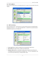
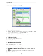
Page 18: ... timeout Alive Timeout Send an ack package when timeout If no response disconnect the section 5 12 TCP Command Settings Enable Enable or disable TCP Command port Listen Port Port number Idle time same as Web server settings Alive timeout same as Web server settings Please refer to the Appendix A for the Command set 5 13 Serial Console and Debug Port Settings Serial Message Enable Enable serial con...

Page 19: ...ug message option Please refer to the Appendix A for the Command set 5 14 Accessible IP Settings You can limit the user IP to access Aport 212 by the Accessible IP settings Aport 212 will check if the remote IP comes from the allowed IP address If not it will deny the connection 0 0 0 0 stands for no restriction in access ...

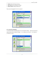
Page 20: ...ide 16 5 15 Alive Check Timeout This setting allows user to configure the Alive Timeout settings for UART1 and UART2 5 16 Quick Command Button Upgrade Firmware Use this button to upgrade Aport 212 firmware if necessary ...

Page 21: ...ings to Aport 212 Disconnect This button can use to stop the serial UART operation TCP console or Web Console 5 17 Web Console Web console allows user to use web browser to configure Aport 212 To open the web console enter the IP address and port number as http 192 168 2 127 5003 User can use Web browser to configure the Basic setting of Aport 212 ...

Page 22: ...t console port and serial console to write their own manager utility software Make sure the Command option is Enable in TCP Command Setting and Serial Console setting The Command format is G S Command Parameter carriage return For example G ip_ip Will get the ip address A p_ip 192 168 2 127 All command are terminated by a carriage return 0x0d Remember to save and reboot the Aport 212 by command S ...

Reviews: