44
2
VMIVME-3126A High Resolution, Isolated Analog-to-Digital Converter Board
RTD Applications and Configurations
The two main configurations for RTDs are the three- and four-wire interfaces. Each of
these configurations will be described, along with figures showing the necessary
connections.
Three-Wire RTD Configuration
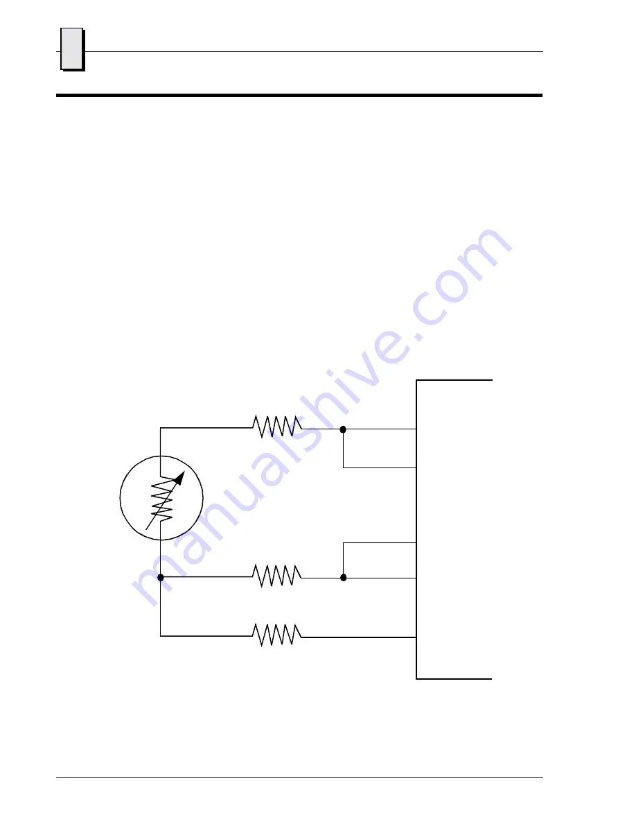
In the three-wire configuration, shown in Figure 2-7 below, lead resistances will result
in errors in the measurement if only one of the RTD excitation currents is used. This is
because the current will flow through
R
L1
developing a voltage error between inputs
CH_H
and
CH_L
. The second RTD excitation current is used to compensate for this error
by suppling the same current through
R
L2
. Assuming the lead resistances are equal,
due to being the same material and same length, and the RTD sources match, the error
voltages generated will match and no error voltage will be developed between the
input pins. Twice the voltage is developed across
R
L3
as a common-mode voltage and
will not introduce any errors.
Figure 2-7 Three-Wire RTD Configuration
R
L1
R
L2
R
L3
P3 or P4
Front Panel Connector
RTD1
HIGH
LOW
AGND
RTD2
RTD
Artisan Technology Group - Quality Instrumentation ... Guaranteed | (888) 88-SOURCE | www.artisantg.com


