55
Control Registers
3
Select Channel Register (SCR)
The Select Channel Register (SCR) selects the channels for calibration or reconfiguration.
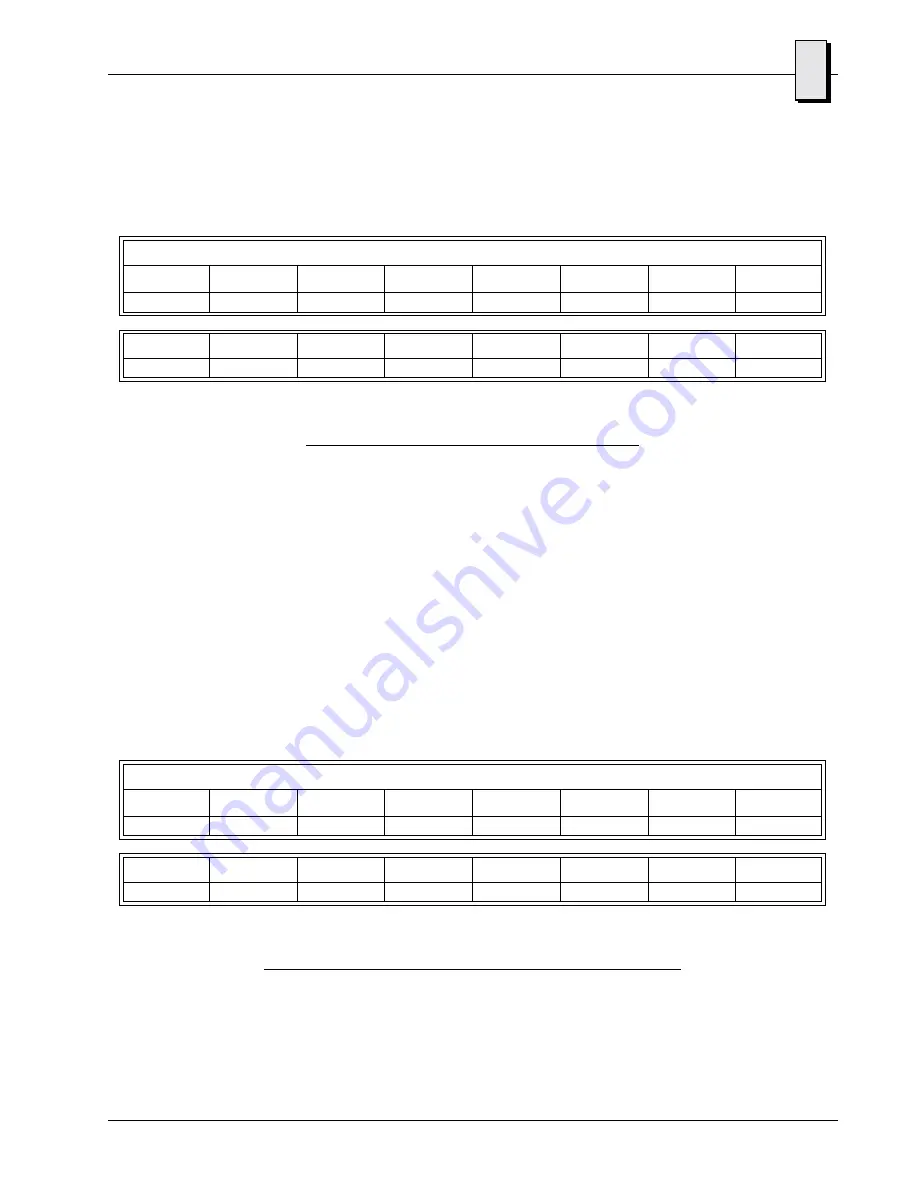
See Table 3-7 below for the Select Channel Register’s bit map.
Powerup/Reset Default = $0000
Select Channel Register Bit Definitions
Bits 15 through 00:
CH [15...0]
- A logical zero (0) written to the bit field inhibits that
channel. logical one (1) written to the bit field enables that
channel for calibration or reconfiguration. After calibration or
reconfiguration is complete, the bit is reset to a logical zero (0).
(Default is logic zero [0].)
Channel Pass/Fail Status Register (PFS)
The Channel Pass/Fail Status (PFS) register contains pass/fail status of the self-test
performed on the ADCs during the powerup/reset condition. It also contains status after
performing open sensor detection.
Powerup/Reset Default = $0000
Channel Pass/Fail Status Register Bit Definitions
Bits 15 through 00:
CH [15...0] -
A logical zero (0) indicates the channel has passed. A
logical one (1) indicates the channel has failed. (Default is logic
zero [0].)
Table 3-7 Select Channel Register’s Bit Map
Select Channel Register (Offset $0006) Read/Write, Byte/Word
Bit 15
Bit 14
Bit 13
Bit 12
Bit 11
Bit 10
Bit 09
Bit 08
CH15
CH14
CH13
CH12
CH11
CH10
CH9
CH8
Bit 07
Bit 06
Bit 05
Bit 04
Bit 03
Bit 02
Bit 01
Bit 00
CH7
CH6
CH5
CH4
CH3
CH2
CH1
CH0
Table 3-8 Channel Pass/Fail Status Register’s Bit Map
Channel Pass/Fail Status Register (Offset $0008) Read Only, Byte/Word
Bit 15
Bit 14
Bit 13
Bit 12
Bit 11
Bit 10
Bit 09
Bit 08
CH15
CH14
CH13
CH12
CH11
CH10
CH09
CH08
Bit 07
Bit 06
Bit 05
Bit 04
Bit 03
Bit 02
Bit 01
Bit 00
CH7
CH6
CH5
CH4
CH3
CH2
CH1
CH0
Artisan Technology Group - Quality Instrumentation ... Guaranteed | (888) 88-SOURCE | www.artisantg.com


