background image

33 


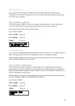
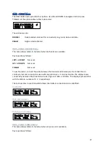
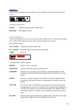
The display shows a real-time analysis of the test. 

The transmit DMX timing is: 

Parameter  Value 

Data Slots 

512 

Break 

96us 

MaB 

12us 

ISD 

0us 

MbB 

16us 


When would I use this? 

If you suspect that something in the DMX infrastructure (Splitter, cable) is causing interference with 
the data, this allows you to transmit high speed data packets and confirm they are received 
correctly. 

NB. This test will almost certainly fail with mergers because they are designed to drop unexpected 
data packets. This is intended for splitters and cables. 


Summary of Contents for Micro-Scope 3c

Page 1: ...Micro Scope 3c User Guide Artistic Licence Engineering Ltd Firmware v1 7 User Guide v8 3 ...

Page 2: ...2 ...

Page 3: ... RECEIVE DECIMAL Menu 16 DMX RECEIVE SINGLE Menu 16 DMX RECEIVE 16 BIT Menu 17 DMX RECEIVE FLICKER Menu 17 DMX RECEIVE STATS Menu 19 DMX RDM Menu 20 DMX RDM DISCOVER Menu 20 DMX RDM PATCH Menu 21 Get the start address of the first root device 22 Get the start address of the second root device 22 Get the start address of the second device s second sub device 22 Set the start address of the first ro...

Page 4: ... ADVANCED Menu 31 DMX ADVANCED LOOP Menu 31 DMX ADVANCED FIX RX Menu 32 DMX ADVANCED NETWORK Menu 32 DMX ADVANCED BOBULATE Menu 34 DMX CABLE Menu 37 DMX CABLE DOUBLE Menu 37 Good cable 37 Data cores swapped 37 Broken ground screen 37 DMX CABLE SINGLE Menu 37 Good cable 38 Data cores swapped 38 CALC Menu 38 UTILS Menu 39 UTILS CONFIG Menu 39 UTILS BACKLIGHT Menu 40 Glossary 41 Channel 41 Slot 41 Da...

Page 5: ...5 Compliance 42 Waste Electrical Electronic Equipment WEEE 42 ...

Page 6: ...6 ...

Page 7: ...le XLR5 on the right panel Pin out is as follows Pin Function Pin 1 Signal Common Pin 2 DMX Transmit Signal Pin 3 DMX Transmit Signal Pin 4 Scope Trigger Output Pin 5 Scope Trigger Ground DMX input The DMX input connection is made via the male XLR5 on the right panel Pin out is as follows Pin Function Pin 1 Signal Common Pin 2 DMX Receive Signal Pin 3 DMX Receive Signal Pin 4 Pin 5 Power Micro Sco...

Page 8: ...lity issue select DMX ADVANCED FIX and leave the Micro Scope in situ for the show NB Disable the standby timer and ensure it is connected to the charge Menu Navigation Menu navigation is intuitive and will be familiar to users of other Artistic Licence products At a given time the product is either in menu mode or run mode The MENU key switches between these modes The figure below shows the top me...

Page 9: ...GHT key to access the relevant sub menus The DMX sub menus are TRANSMIT Transmit test patterns of DMX to dimmers or fixtures RECEIVE Receive and view DMX levels plus analyse timing RDM Discover configure and monitor RDM devices ADVANCED Test the DMX network fix bad DMX and access our unique discombobulator CABLE Test connectivity of the three DMX conductors DMX TRANSMIT Menu The DMX TRANSMIT menu ...

Page 10: ...e level of the selected channel When would I use this This is the classic rig check mode that allows you to cycle through all the channels checking the lighting rig lamp by lamp DMX TRANSMIT RANGE Menu This menu allows transmission of a range of channels Keys operate as follows LEFT and RIGHT Navigate through the option fields In the product option fields are shown in UPPER CASE In this guide opti...

Page 11: ...k and edit any of the forty scenes The scenes are saved in flash memory and so will be available between power cycles and even when batteries are removed Keys operate as follows LEFT and RIGHT Navigate through the option fields In the product option fields are shown in UPPER CASE In this guide option fields are highlighted in red UP and DOWN Select the required value within an option field TOGGLE ...

Page 12: ...is used to set numerous DMX transmit parameters This menu should be used with caution as it intentionally allows the user to set parameters which result in illegal DMX transmission For this reason the parameters are not saved across a power cycle The values set in this menu will be used for DMX TRANSMIT CHANNEL DMX TRANSMIT RANGE and DMX TRANSMIT SCENE Keys operate as follows LEFT and RIGHT Naviga...

Page 13: ...s 20ms 0us 1s 3 1 This is a simplification that provides a good rule of thumb In fact any number of data slots below 24 can be used subject to Packet Time 1204us 2 In the earlier DMX512 1990 standard the minimum was 88us 3 The 1s maximum is actually for the entire packet 4 In the earlier DMX512 1990 standard the minimum was 8us When would I use this These parameters are used when testing a DMX rec...

Page 14: ...play a decimal hexadecimal and a high resolution bargraph of two consecutive channels expressed as 16 bit Big Endian FLICKER Display the decimal level of a single channel along with the maximum and minimum levels detected STATS Display statistics and detailed timing for received DMX DMX RECEIVE STATUS Menu The DMX RECEIVE STATUS menu is used to display to total number of received DMX packets and c...

Page 15: ...of the levels of up to 24 consecutive channels Keys operate as follows LEFT and RIGHT Select the required start address for the received DMX display The display will change to show the first and last channel displayed UP and DOWN Select the required start address for the received DMX display The display will change to show the first and last channel displayed TOGGLE Cycles through the GRAPH DECIMA...

Page 16: ...ws LEFT and RIGHT Select the required start address for the received DMX display The display will change to show the first and last channel displayed UP and DOWN Select the required start address for the received DMX display The display will change to show the first and last channel displayed TOGGLE Cycles through the GRAPH DECIMAL SINGLE 16 BIT receive menus The left of screen shows the DMX addre...

Page 17: ...ws LEFT and RIGHT Select the required start address for the received DMX display The display will change to show the first and last channel displayed UP and DOWN Select the required start address for the received DMX display The display will change to show the first and last channel displayed TOGGLE Cycles through the GRAPH DECIMAL SINGLE 16 BIT receive menus The left of screen shows the DMX addre...

Page 18: ...he current received level is 253 In the example below the current received level is 253 but the min max range is now 000 255 showing that flicker has been captured The left of screen shows the DMX address along with the Insight icon display The levels displayed are from the received DMX of the start code defined in DMX RECEIVE STATUS When would I use this Flickering can be caused by many condition...

Page 19: ...on to the Start Code that are contained in the DMX packet 0 512 Break The Break is the synchronization that indicates the start of DMX packet 88us 1s 3 MaB The MaB or Mark after Break is the idle period between the end of Break and the Start Code 8us 1s 3 ISD The ISD is the inter slot delay This is the idle time between the slots in the DMX packet 0us 1s 3 MbB The MbB or Mark before Break is the i...

Page 20: ... Set all RDM parameters SENSORS Read all device sensors DMX RDM DISCOVER Menu RDM devices must be discovered before they can be controlled This function is used to discover and enumerate all the connected RDM devices Keys operate as follows LEFT and RIGHT Not used UP and DOWN Select the required action TOGGLE Start discovery Discovery can take a few seconds and will be longer when more devices are...

Page 21: ...ion as follows DEV Selects the RDM device Devices are numbered from 1 A value of zero is displayed as ALL and indicates that all RDM devices are being controlled This is a very powerful feature but should be treated with caution as it allows for example all start addresses to be set to the same value NB The device number is enumerated during discovery and numbers are allocated in the order in whic...

Page 22: ...dates to report that the device is called sunDial 2 and has a start address of 005 and a personality of 001 Get the start address of the second device s second sub device Use the LEFT RIGHT UP DOWN keys to set the device to 002 shown in green This is the second sunDial Use the LEFT RIGHT UP DOWN keys to set the sub device to 002 shown in blue This means the second sub device is being accessed The ...

Page 23: ...hows the total number of programmed devices and the backlight will blip green or red to indicate success or whether errors occurred When would I use this This is a quick and dirty way to ensure all devices have different and contiguous addresses However you have no control over which device gets which start address In many situations this does not matter as the lighting console patch will make it ...

Page 24: ...re being controlled NAME When an individual device or sub device is addressed the name of the device or sub device is displayed here If ALL devices and or ALL sub devices is selected BROADCAST is displayed The following example shows how this is used We are connected to an Artistic Licence sunDial dimmer Get the status messages from the first root device Use the LEFT RIGHT UP DOWN keys to set the ...

Page 25: ...ufacturer specific PIDs are allowed where the RDM standard does not have a suitable definition Micro Scope 3c interrogates the selected device sub device combination and allows all supported PIDs to be accessed DATA The data that is read get or to be programmed set into a parameter NB The first release firmware has limited support for manufacturer specific parameters as the RDM standard is current...

Page 26: ...hown in blue This means the root device is being accessed Change the start address to the desired value value 050 shown in green and press TOGGLE Micro Scope 3c will set the value and briefly display the response from the device This will either be an ACK which is good or a NACK with additional information that explains the reason that the device could not accept the command Micro Scope 3c will th...

Page 27: ...arameter PID 0x0000 Format error The RDM device believes the command sent by Micro Scope 3c is badly formatted 0x0001 Hardware fault The RDM device cannot action the command due to a hardware fault 0x0002 Proxy reject The RDM device received a proxy failure 0x0003 Write protected The RDM device is write protected and so rejected the set command 0x0004 Unsup cmd class The RDM device reports an unsu...

Page 28: ...absent The RDM device reports that the sub device or sensor addressed in the command is absent This is used on modular products where the sub device or sensor can be physically disconnected 0x0014 Sens out of range The RDM device reports that the sensor is out of range 0x0015 Sensor fault The RDM device reports that the sensor is faulty 0x0016 Packing not supp The RDM device reports that the PID i...

Page 29: ...r may change when discovery is next executed SUB Selects the sub device An RDM device may have a number of sub devices and Micro Scope 3c is able to access 999 sub devices There are two special cases of sub device Zero accesses the root device ALL indicates that all sub devices are being controlled SEN The currently selected sensor If the device has no sensors this field will get set to zero NAME ...

Page 30: ...30 When would I use this When a particular device is suspected of a fault this allows you to continuously monitor sensors ...

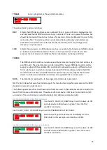
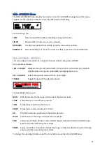
Page 31: ...is guide option fields are highlighted in red UP and DOWN Select the required value within an option field TOGGLE Toggle the level of the selected channel The operating functions are MAN DMX transmitted to the range of channels at the selected level SNAP Snap between on and off every second FADE Slowly fades to full then back to zero RAMP Slowly fades to full and rolls over to zero ALT Odd channel...

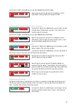
Page 32: ...nnect Micro Scope 3c between them using this function If the problem was solved you have your answer Additionally Micro Scope remembers the last menu when power cycled so this is useful when you always want Micro Scope to boot in Fix mode DMX ADVANCED NETWORK Menu This function uses the DMX test packet to check for data loss in a DMX network The output of Micro Scope 3c should be connected to the ...

Page 33: ... use this If you suspect that something in the DMX infrastructure Splitter cable is causing interference with the data this allows you to transmit high speed data packets and confirm they are received correctly NB This test will almost certainly fail with mergers because they are designed to drop unexpected data packets This is intended for splitters and cables ...

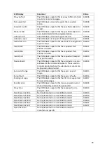
Page 34: ... DMX with a 512 data slot payload and all levels at zero All DMX receivers should accept this Legal packet 200uS 20us 0 0 513 512 0 16us Test pack Micro Scope 3c transmits the special test packet with a very fast set of timing Receivers that do not correctly reject non zero start codes will sometimes flicker when receiving this Legal packet 96uS 12us 85 0 513 512 85 16us Bad RDM Micro Scope 3c tra...

Page 35: ...ak Strt Micro Scope 3c continuously sends a break and start code with no slots Some DMX responders can be upset by this Legal packet 200us 20us 0 n a 1 0 n a n a Long pack Micro Scope 3c sends packets with 1000 data slots This is primarily useful for development testing Illegal packet 200us 20us 0 0us 1001 1000 0 16us Short pack Micro Scope 3c sends packets with 8 data slots but very fast timing a...

Page 36: ...Scope 3c sends packets with slots containing only one stop bit This is primarily useful for development testing Illegal packet 200us 20us 0 4us 513 512 0 16us As at firmware v1 3 the above table is still under verification and minor errors may exist When would I use this A well designed DMX or RDM receiver will reject bad DMX and continue to operate normally when it received good DMX These functio...

Page 37: ...t the cable between the transmit and receive pins Note that this is a continuity test and so cannot be used with any electronics it only tests cable The display shows connectivity between the three main circuits of ground data and data The display represents this with the XLR pin numbers of 1 2 3 respectively The test operates in real time which allows intermittent connections to be identified Goo...

Page 38: ...en pins 2 3 as shown below Data cores swapped If there is a low impedance path between pins 2 3 a fault is shown Note that this will also detect a termination on the line CALC Menu The CALC menu provides a simple decimal hexadecimal binary dip switch calculator Keys operate as follows LEFT and RIGHT Set the desired digital value UP and DOWN Set the desired digital value TOGGLE Toggle the digital v...

Page 39: ... product has been booted USER NAME TOGGLE user owner name of 10 characters This will be displayed on boot splash screen Warning This field is only editable when the Boot Count is less than 50 USER CO Enter user owner company of 10 characters This will be displayed on boot splash screen Warning This field is only editable when the Boot Count is less than 50 ST BY TIME The time in minutes that Micro...

Page 40: ...s operate as follows LEFT and RIGHT Navigate through the option fields UP and DOWN Select the required value within an option field TOGGLE Not used The option fields function as follows NORMAL Intensity of backlight in normal menu operation VISUAL YES Some menus use visual feedback This is the intensity for good or yes VISUAL NO Some menus use visual feedback This is the intensity for bad or no Ba...

Page 41: ...t is the formal name for Channel Footprint The number of channels or data slots that a DMX receiver uses Personality Personalities allow RDM devices to have different setups that can be selected via RDM RDM Remote Device Management Refresh rate This repeat rate of DMX512 data The maximum refresh rate of DMX with a full 512 channel payload is 44Hz Get The RDM term meaning to read a parameter Set Th...

Page 42: ...ss a request to return goods please email Sales ArtisticLicence com No user serviceable parts inside Compliance All Products manufactured or sold by Artistic Licence Engineering Ltd are fully compliant with the appropriate UKCA CE and RoHS regulations Product specific information is available on request Waste Electrical Electronic Equipment WEEE Artistic Licence is a member of a WEEE compliance sc...

Page 43: ...Licence Engineering Ltd makes no warranty of any kind with regard to this material including but not limited to the implied warranties of fitness for a particular purpose Artistic Licence Engineering Ltd shall not be liable for errors contained herein or for incidental or consequential damages in connection with the furnishing performance or use of this material All trademarks are acknowledged Sin...

Reviews: