67
Marker Physical Setup
The marker should be prepared to run as prescribed in the markers manual. Position the marker in line with the
wire path of the
CR
using a marker bar or suitable stand or table. Connect specified air and power supply. It is
important that the position of the marker relative to the
CR
cutter blades remain stable and not be allowed to shift
during wire processing. Connect the marker interface cable to the
CR
.
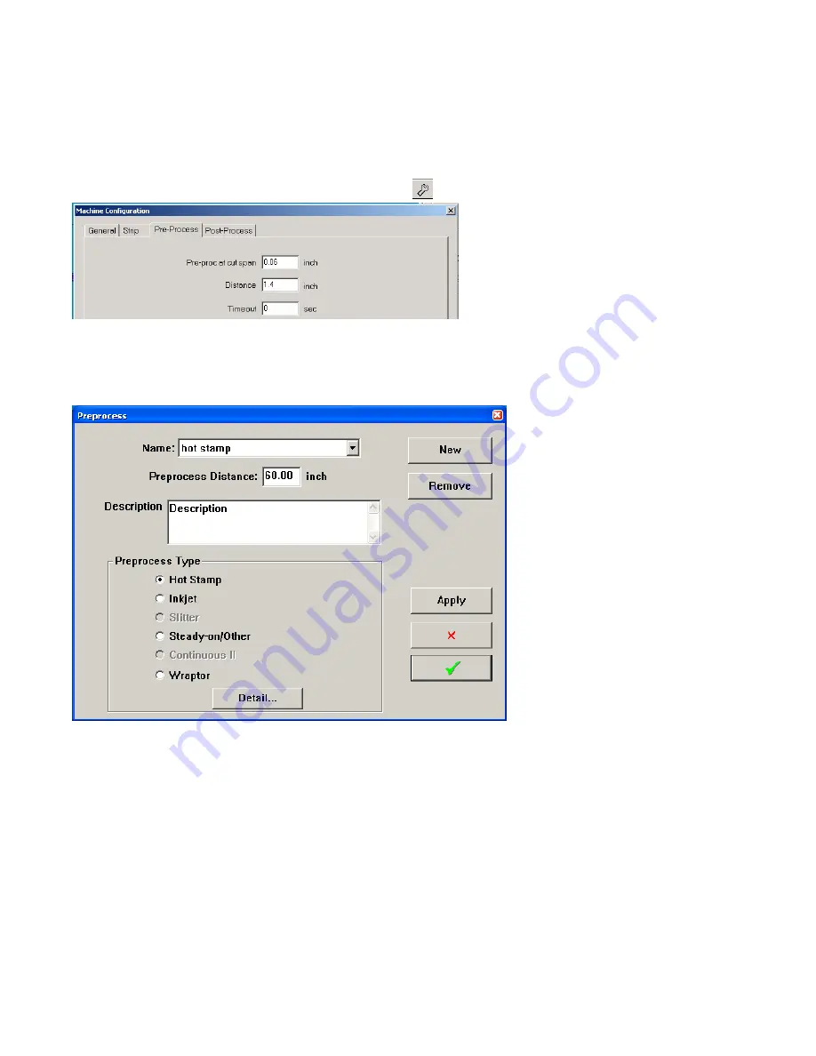
Measure the distance from the center of the marker to the cut-off blade
Distance value is entered in the Preprocess configuration
window but can be adjusted here.
HOT STAMP MARKING
Hot Stamp marking uses a WM-6 or third party marking device to place a hot inked foil transfer mark on the wire.
The CR allows several formats for these marks.
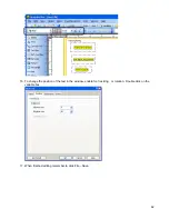
The PreProcess window allows you to select from existing preprocesses or make a new one. Click on
Detail Setting
and
the window below will open.
WM6
With the WM 6 two type sets are used. This allows for same or unique making on either end of the wire as depicted at the
bottom of the window. The wire will be cut between the marks. Using a single type holder or two holders that make up one
message makes the WM 6 useable in any of the Hot Stamp configurations.
A single-type holder marker cannot practically be used as a WM 6 type marker.


