6
Masaüstünü Göster.scf
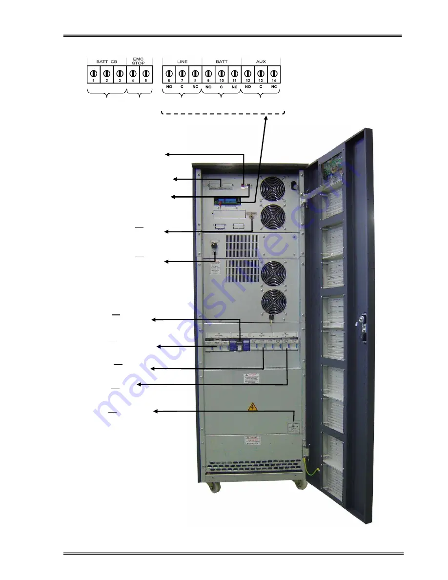
Figure 1.3
30-40 kVA Switch configuration
RS232
Communication Port
(DB9 Female)
Dry Relay Output Contacts
Battery circuit
breaker Input
Emergency
Stop
Line Failure
Relay
Battery Low
Relay
( RS232 / SNMP )
Communication
Select Switch
S7
ON / OFF
Switch
S5
(Battery Input, F10-F11-F12)
S1
(AC Input, F1-F2-F3)
S3
(Maintenance by-pass)
(Under the cover)
S2
(By-Pass, F4-F5-F6)
S4
(AC Output, F7-F8-F9)
By-Pass
Relay
Parallel Com. Ports.
S6
Manual Bypass
Switch
Summary of Contents for ARTon Plus series
Page 1: ...SERVICE TRAINING NOTES ARTon Plus SER S UPS 10 15 20 30 40 kVA 3 Faz Giri 3 Faz k...
Page 2: ......
Page 13: ...9 Figure 1 4 2 IGBT Rectifier...
Page 14: ...10 Figure 1 4 3 Transformerless 3 Phase Inverter...
Page 15: ...11 Figure 1 4 4 ARTonPlus series UPS Basic Diagram...
Page 21: ...17 Figure 1 5 3 PFC3P R1 Board...
Page 23: ...19 Figure 1 5 4 IPMD3P Board...
Page 28: ...24 Figure 1 5 5 P3MC R5 Board...
Page 31: ...27 Figure 1 5 6 ADVS01 R1 Board...
Page 33: ...29 Figure 1 5 7 SDXC300 R1 Board...
Page 36: ...32 Figure 1 5 9 ITF3 R2 Board...
Page 39: ...35 Figure 1 5 11 OPS3 Board...
Page 40: ...36...
Page 41: ...37...
Page 42: ...38...
Page 73: ......
Page 74: ...1 AGKK7080 01 2008...


