33
1.5.9 STM01 OUTPUT MONITORING BOARD
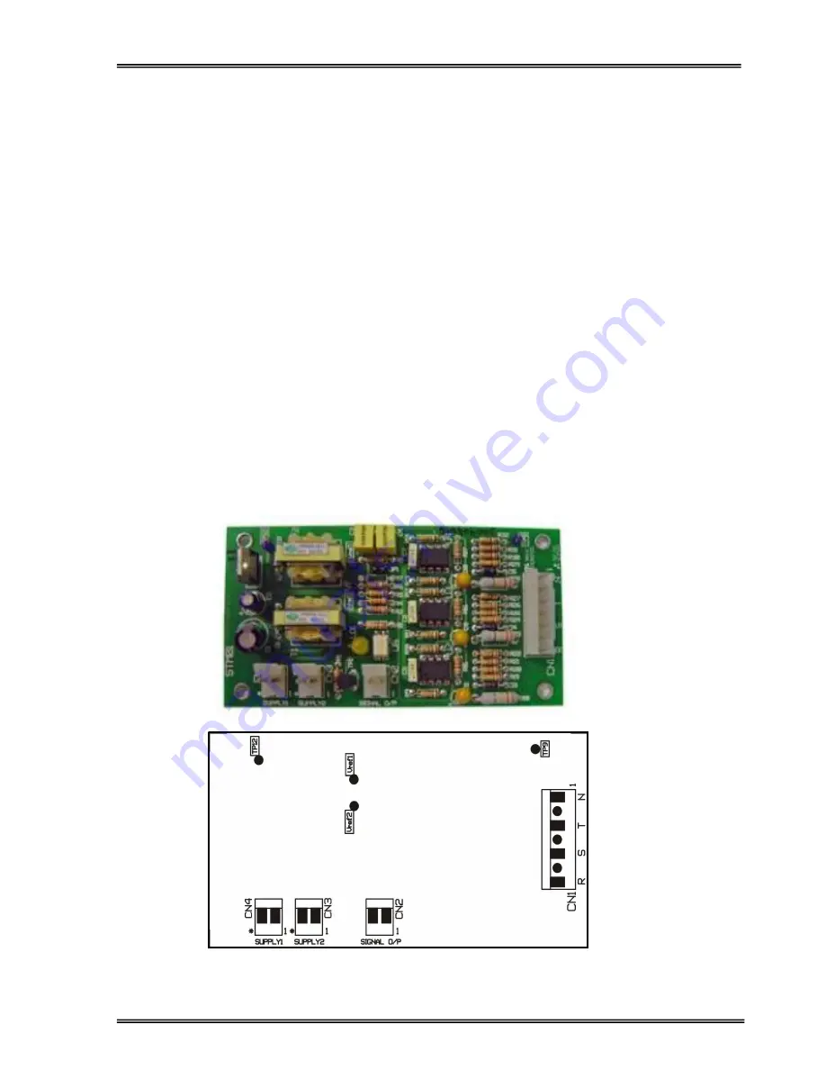
This board monitors the UPS output voltages. It accepts the 3-Phase AC output voltages at the UPS output
and generates a fault signal if there is a voltage or alternance loss in the outgoing sinusoidal waveforms.
A)
STM01 Board Connectors
- CN1 : The 3-phase and Neutral of UPS output voltages (the output of the SCR switches) are
connected to this socket. If any one of these voltages is too low (<160V AC) or has a high DC
component (probably resulting from inverter damage, bad connection or SCR failure etc.) then
a ‘’DC fault’’ signal is produced on this board.
CN1-1 : Neutral
CN1-3 : UPS output T-phase
CN1-5 : ‘’ S-phase
CN1-7 : ‘’ R-phase
- CN2 : When a ‘’DC fault’’ signal is produced, it is available on this socket. This is indicated by LD1
(yellow LED). CN2 is connected to CN9 of ADVS01-R1 board and the fault signal is
transferred to the main controller board (P3MC-R5) from ADVS01 board.
- CN3 : HF supply input
- CN4 : HF supply input
B)
STM01 Board Test Points
- TP12 : +12V DC(+/-0.5V)
- TP : VREF1 = 7.7V DC (+/-0.2V)
- TP : VREF2 = 6.7V DC ( ‘’ )
Figure 1.5.10 STM01 Board
Summary of Contents for ARTon Plus series
Page 1: ...SERVICE TRAINING NOTES ARTon Plus SER S UPS 10 15 20 30 40 kVA 3 Faz Giri 3 Faz k...
Page 2: ......
Page 13: ...9 Figure 1 4 2 IGBT Rectifier...
Page 14: ...10 Figure 1 4 3 Transformerless 3 Phase Inverter...
Page 15: ...11 Figure 1 4 4 ARTonPlus series UPS Basic Diagram...
Page 21: ...17 Figure 1 5 3 PFC3P R1 Board...
Page 23: ...19 Figure 1 5 4 IPMD3P Board...
Page 28: ...24 Figure 1 5 5 P3MC R5 Board...
Page 31: ...27 Figure 1 5 6 ADVS01 R1 Board...
Page 33: ...29 Figure 1 5 7 SDXC300 R1 Board...
Page 36: ...32 Figure 1 5 9 ITF3 R2 Board...
Page 39: ...35 Figure 1 5 11 OPS3 Board...
Page 40: ...36...
Page 41: ...37...
Page 42: ...38...
Page 73: ......
Page 74: ...1 AGKK7080 01 2008...


