46
III. FRONT PANEL
3.1 Introduction
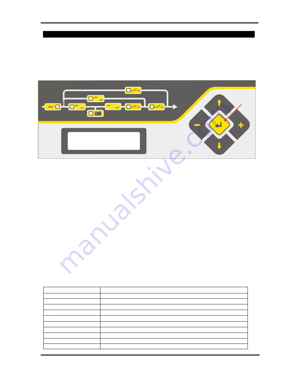
The front panel of UPS, consisting of a 2 lines alphanumeric display, 7 status lamps, plus 5 function keys,
allows the complete monitoring of the UPS status. The mimic flow diagram helps to comprehend the
operating status of the UPS. By using the function keys operator can moves on menus and change some
parameters.
Figure 3. Operator control and indicator panel
L1
: If lamp is lit mains is okay
L2
: If lamp is lit the rectifier is operating
L3
: If lamp is lit UPS is operating on batteries
L4
: If lamp is lit static bypass is active and load is supplied by the bypass source.
L5
: If lamp is lit mechanical bypass switch is on
L6
: If lamp is lit inverter supplies the load
L7
: If lamp is lit the output switch is “ON”.
There are 5 function keys on front panel. These are ENTER
(
)
, UP
(
↑
)
, DOWN
(
↓
)
, PLUS
(+)
and MINUS
(-)
.UP and DOWN keys help moving on menus, PLUS and MINUS keys select options, ENTER key means
the selected option or menu is valid.
3.2 Front Panel Menu Descriptions
By using the buttons on the front panel, you can move on main menu functions. You can enter the
submenus of the item seen on the LCD panel (MEASURES, ALARMS, INFORMATION etc.) and navigate
within it by using (
↓)
, (
↑
) and ENTER keys.
The Main Menu items are listed below. You can choose any requested menu using (
↑
) and (
↓)
keys. By
pressing ENTER key, you can choose that menu and you can reach all submenu items using (
↑
) and (
↓)
keys again. At the end of submenus of each MENU, an <ENTER> EXIT message is seen, and if you press
ENTER, you exit from the selected menu and go back to the beginning of the Main Menu.
Main Menu items
Function
STATUS MENU
The status message which shows the UPS status
MEASURES MENU
Enter
"go to Meausures submenu"
ALARMS MENU
Enter
"go to Alarms submenu"
INFORMATION MENU
Enter
"go
to İnformation submenu"
ADJUST MENU
Enter
"go to adjust submenu"
OPTIONS MENU
Enter
“go to options submenu”
COMMAND MENU
Enter
“go to Command submenu”
TIME MENU
Enter
“go to Time and date submenu”
SERVICE MENU
Enter
“go to service submenu”
Go to STATUS MENU
L1
L2
L3
L4
L6
L7
ENTER
L5
Summary of Contents for ARTon Plus series
Page 1: ...SERVICE TRAINING NOTES ARTon Plus SER S UPS 10 15 20 30 40 kVA 3 Faz Giri 3 Faz k...
Page 2: ......
Page 13: ...9 Figure 1 4 2 IGBT Rectifier...
Page 14: ...10 Figure 1 4 3 Transformerless 3 Phase Inverter...
Page 15: ...11 Figure 1 4 4 ARTonPlus series UPS Basic Diagram...
Page 21: ...17 Figure 1 5 3 PFC3P R1 Board...
Page 23: ...19 Figure 1 5 4 IPMD3P Board...
Page 28: ...24 Figure 1 5 5 P3MC R5 Board...
Page 31: ...27 Figure 1 5 6 ADVS01 R1 Board...
Page 33: ...29 Figure 1 5 7 SDXC300 R1 Board...
Page 36: ...32 Figure 1 5 9 ITF3 R2 Board...
Page 39: ...35 Figure 1 5 11 OPS3 Board...
Page 40: ...36...
Page 41: ...37...
Page 42: ...38...
Page 73: ......
Page 74: ...1 AGKK7080 01 2008...


