52
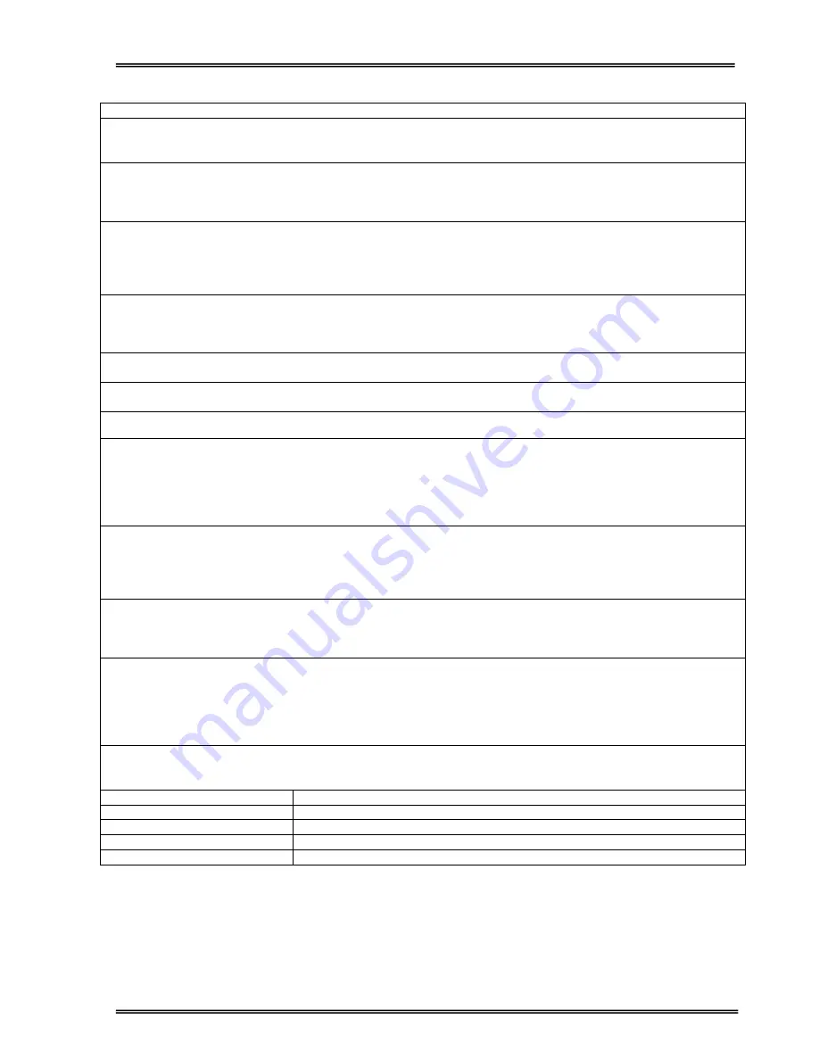
ALARM
DESCRIPTION
A9 OVERLOAD
UPS loaded more than 100% of nominal power rating.
Possible Causes:
This state is may be continous or temporary. When this alarm is continous
check the loads connected to the UPS output.
A10 LINE FAILURE
Line failure.
Possible Causes:
1) Mains may be off.
2) Check all three input phases.
3) Check UPS input fuses.
A11 HIGH TEMPER
Overtemperature
1) Overload for inverter
2) Excessive ambient temperature.
3) Fan failure or dirty air inlets
4) Bad UPS location (not enough ventilation)
A12 OVERCURRENT
Inverter output system failure
1) Internal overcurrent
2) Output short circuit.
3) UPS failure. Call the service.
A13 OUTPUT LOW
Inverter output voltage is lower than the min tolerated value.
Inverter is stopped.
A14 BATTERY HIGH
Battery voltage is higher than max. tolerated value for batteries. (either positive
or negative battery groups)
A15 FUSE FAILURE
Blown fuse(s). (not used in this power range)
A16 BYP INPUT BAD
During transfer to bypass, Voltage or frequency value of bypass source
is incorrect and the UPS turns off the load power.
During normal (inverter) operation some times you can see this message due
to fluctuations in bypass supply.
During bypass if the bypass protection option is “ON” and if the bypass source
is out of tolerance UPS switches off the static bypass for load protection.
A17 BATT CB OPEN
Battery circuit breaker is off ,batteries are not connected to UPS
At start up If the mains is okay you can start operation having this message
active.
At start up during line failure UPS waits for the battery CB to be turned on and
then starts.
A18 BATT.CAPA.LOW
If the battery charge level is low this message indicates that charge period is
not completed yet. If mains failure occurs during this message, battery
operation time may be unexpectedly short.
UPS gives beep sound every 15 sec
A19 BATT FAULT
Battery test aborted. And batteries are not OKAY
UPS gives beep sound every 15 sec
You can clear this message by pressing the ENTER key for 3 seconds.
Possible Causes:
1) Rectifier fault
2) Damaged battery cells
3) Poor battery connections
A20 BOOST CHARGE
Boost charge is active. At the end of the boost charging time UPS stops the
boost charge.
UPS gives beep sound every 15 sec
A23 MODE FAILURE
In parallel system, the operation mode of the UPS is different from the others.
A24 P.FAILURE 17
Parallel controller board failure
A25 P.FAILURE 18
Parallel controller board failure
A26 P.FAILURE 19
Parallel controller board failure
A27 P.FAILURE 20
Parallel controller board failure
Summary of Contents for ARTon Plus series
Page 1: ...SERVICE TRAINING NOTES ARTon Plus SER S UPS 10 15 20 30 40 kVA 3 Faz Giri 3 Faz k...
Page 2: ......
Page 13: ...9 Figure 1 4 2 IGBT Rectifier...
Page 14: ...10 Figure 1 4 3 Transformerless 3 Phase Inverter...
Page 15: ...11 Figure 1 4 4 ARTonPlus series UPS Basic Diagram...
Page 21: ...17 Figure 1 5 3 PFC3P R1 Board...
Page 23: ...19 Figure 1 5 4 IPMD3P Board...
Page 28: ...24 Figure 1 5 5 P3MC R5 Board...
Page 31: ...27 Figure 1 5 6 ADVS01 R1 Board...
Page 33: ...29 Figure 1 5 7 SDXC300 R1 Board...
Page 36: ...32 Figure 1 5 9 ITF3 R2 Board...
Page 39: ...35 Figure 1 5 11 OPS3 Board...
Page 40: ...36...
Page 41: ...37...
Page 42: ...38...
Page 73: ......
Page 74: ...1 AGKK7080 01 2008...


