58
Note:
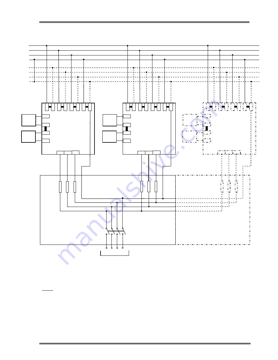
As seen in the figure, the outputs of parallel UPS units should be connected to each other using an
AC distribution board.
ATTENTION!!! The cables from each UPS output to the distribution board must be of the same
size and length for proper load sharing during parallel operation.
BATTERIES
Figure 4.3
ARTonPlus Series Parallel UPS Power Connections
U V W N
LOAD
FUSES
AC OUTPUT
BYPASS AC INPUT
MAIN AC INPUT
AC DISTRIBUTION BOARD
U1
V1
W1
N1
U2
V2
W2
N2
+
-
+
-
UPS1
K3
K2
K2
K
4
K
5
K
6
K
7
K
8
K
9
K
10
K
11
K12 K13 K14
K1
U
V W N
AC OUTPUT1
+
-
+
-
BATTERIES
UPS2
K3
K2
K2
K
4
K
5
K
6
K
7
K
8
K
9
K
10
K
11
K12 K13 K14
K1
U
V W N
AC OUTPUT2
FUSES
+
-
+
-
BATTERIES
UPS3
K3
K2
K2
K
4
K
5
K
6
K
7
K
8
K
9
K
10
K
11
K12 K13 K14
K1
U
V W
N
AC OUTPUT3
FUSES
LOAD BRAKE
SWITCH
Summary of Contents for ARTon Plus series
Page 1: ...SERVICE TRAINING NOTES ARTon Plus SER S UPS 10 15 20 30 40 kVA 3 Faz Giri 3 Faz k...
Page 2: ......
Page 13: ...9 Figure 1 4 2 IGBT Rectifier...
Page 14: ...10 Figure 1 4 3 Transformerless 3 Phase Inverter...
Page 15: ...11 Figure 1 4 4 ARTonPlus series UPS Basic Diagram...
Page 21: ...17 Figure 1 5 3 PFC3P R1 Board...
Page 23: ...19 Figure 1 5 4 IPMD3P Board...
Page 28: ...24 Figure 1 5 5 P3MC R5 Board...
Page 31: ...27 Figure 1 5 6 ADVS01 R1 Board...
Page 33: ...29 Figure 1 5 7 SDXC300 R1 Board...
Page 36: ...32 Figure 1 5 9 ITF3 R2 Board...
Page 39: ...35 Figure 1 5 11 OPS3 Board...
Page 40: ...36...
Page 41: ...37...
Page 42: ...38...
Page 73: ......
Page 74: ...1 AGKK7080 01 2008...


