5.4.5. RM (Resonance Modulation)
This parameter modulates the level of resonance that will occur at the cutoff frequency of
the filter. It is pre-wired to be modulated by LFO 2, but the patch bay can be used to route
another input as the resonance modulation source.
This control is bi-polar, which means it allows the modulation to be either positive- or
negative-going. It also means that when the knob is set to the center position (12:00) no
modulation will occur.
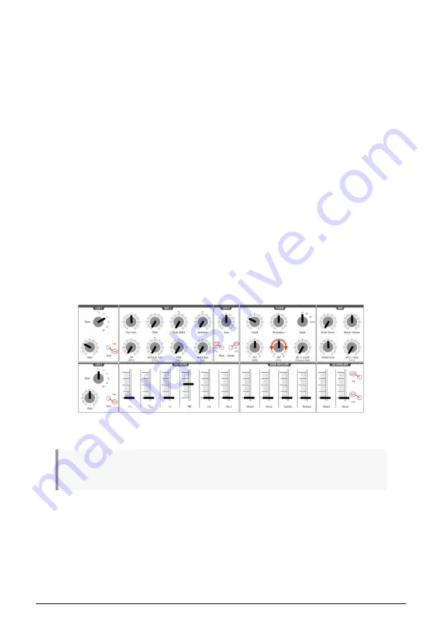
Here's a good experiment to illustrate what the RM parameter does:
• Set all of the OSC MIXER sliders to 0 (lowest position)
• Adjust the
NOISE
generator slider to midrange
• Set all of the filter envelope and amplifier envelope sliders to 0
• Set the filter mode to
LP
• Set the Cutoff knob to the 10:00 position
• Set the Resonance knob to the middle position (12:00)
• Set the LFO 1 waveshape to Sawtooth and the Rate to the 10:00 position
• Play and hold a note
• Slowly turn the RM knob clockwise (positive). At about the 3:00 position you
should hear a falling "chirp" similar to an early electronic drum kit.
• Slowly turn the RM knob counter-clockwise (negative). At about the 9:00 position
you should hear that same "chirp" sound, but it will rise instead of fall. It will
actually sound like a recording of the same drum is being played backward.
Here's a graphic representation of the RM experiment:
♪
: For the technically-minded, you may notice that there is a slight deformation of the RM signal due
to the threshold in the bipolar attenuator circuitry.
Experimenting with RM modulation
Arturia - User Manual MiniBrute 2S - The top panel
37
Summary of Contents for MINIBRUTE 2S
Page 1: ...USER MANUAL...


