background image

ARTURIA – MOOG MODULAR V – USER’S MANUAL 

95 

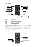
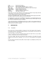
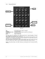
5.2.5 Stereo 

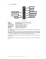
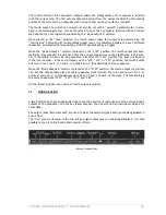
Delay 


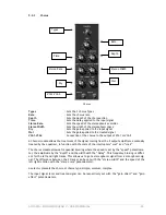
Stereo Delay module 

Midi sync


: Synchronizes delay with the tempo of the host application 

Time left


: Sets the time of the right track 

Time right


: Sets the time of the left track 

Feedback left


: Sets the feedback gain for the right track 

Feedback right


: Sets the feedback gain for the left track 

Feedback to left


: Sets the feedback gain of the right track towards the left track 

Feedback to right


: Sets the feedback gain of the left track towards the right track 

Dry


: Sets the gain applied to the input signal 

Wet


: Sets the gain applied to the treated signal 

VCA1-VCA2


: Connection of the delay to the output of VCA1 or VCA2 


A stereo delay module treats the signal coming from the 2 output amplifiers, eventually treated by 

the equalizer and chorus, in function with the state of the interrupters “vca1” and “vca2”. 


This module allows the repetition of the input signal independently on the left and right tracks, 

which explains the presence of 2 columns of controls.  

The repetition speed can be set with the “time” potentiometer, while the level of the repetitions, 

and eventually the number of audible repetitions is set with the “feedback” potentiometer. The 

third potentiometer sends a part of the treated signal to the other track. 


The repetition speed can be synchronized with the tempo of the host application, and in this case, 

the “time” potentiometer selects the multiples and sub-multiples of this tempo. 


The levels of the input and treated signals can be respectively set with the rotating “gain direct” 

and “gain effect” buttons.  

Midi sync  

Time right 

Time left

Feedback right 

Feedback left 

Feedback to left 

Feedback to right 

Wet 

Dry 

VCA1-VCA2 

Summary of Contents for Moog Modular V

Page 1: ...USER S MANUAL Moog Modular V 2 ...

Page 2: ...her Sadahiro Nakano Fabrice Paumier Ben Turl Peter Willems and the numerous beta testers ARTURIA SARL 1999 2004 All rights reserved 4 Chemin de Malacher 38240 Meylan FRANCE http www arturia com Information contained in this manual is subject to change without notice and does not represent a commitment on the part of Arturia The software described in this manual is provided under the terms of a lic...

Page 3: ...ll command it becomes possible to access all of the mod ules on the same screen a feature that will delight many musicians We have also broadened the configuration possibilities for the synthesizer Some modules can now be interchanged which brings the Moog Modular V closer to the original instruments that could be configured by Moog Music upon order Improvements have also been made to the audio ma...

Page 4: ......

Page 5: ...ion of the synthesis section modules 35 3 4 The other sections 39 3 4 1 The sequencer 39 3 4 2 The effects 42 3 5 the virtual keyboard and its real time controllers 47 3 5 1 The keyboard 47 3 5 2 The keyboard controllers 47 3 5 3 The play modes 49 3 5 4 The sound design controllers 49 4 The interface 53 4 1 Using the presets 53 4 1 1 Choice of bank sub bank preset 53 4 1 2 Creation of a bank sub b...

Page 6: ...6 1 The three main modules 103 6 1 1 The oscillator or VCO 103 6 1 2 The filter or VCF 106 6 1 3 The amplifier or VCA 110 6 2 Complimentary modules 110 6 2 1 The keyboard 110 6 2 2 The envelope generator 110 6 2 3 The low frequency oscillator 111 7 A few elements of sound design 113 7 1 Modular sound synthesis 113 7 1 1 Simple patch n 1 113 7 1 2 Simple patch n 2 114 7 1 3 Complex patch n 1 118 7 ...

Page 7: ... 149 8 3 2 The RTAS and HTDM standards 149 8 3 3 Opening the instrument 150 8 3 4 Connection to a MIDI node 150 8 3 5 Saving presets 150 8 3 6 Automation under Pro Tools 151 8 4 DXi 151 8 4 1 Installation 151 8 4 2 Opening the instrument SONAR 2 0 151 8 4 3 Connection to a MIDI track 151 8 4 4 Saving presets 152 8 4 5 Automation 152 8 5 Digital Performer 152 8 5 1 Installation 152 8 5 2 Opening th...

Page 8: ......

Page 9: ...to listen to a song he had composed Moog is immediately convinced and they decide to associate their work Their co operation produced the first VCO In 1964 the first prototype of a Moog synthesizer was produced It was a modular system with a vol tage controlled filter VCF an envelope generator a white noise generator a trigger and two key boards each with a generator module sawtooth triangle and i...

Page 10: ... the 900 series for commercial sale The R A Moog Company at Trumansburg NY Courtesy of Roger Luther MoogArchives com The first client to buy the full Moog system was choreographer Alwin Nikolais Also among the first users were composers Eric Siday and Chris Swansen The first commercial uses of the Moog synthe sizers were done in advertising They were also used for jingles and in recording studios ...

Page 11: ...It won three Grammy awards Switched On Bach by W Carlos A little later Keith Emerson keyboard player for the groups Nice and ELP Emerson Lake and Pal mer was he himself to become an ambassador for Moog synths He was one of the first to play a Moog modular on stage during a tour A 3C system Jan Hammer was also one of the first users of Moog systems Big groups like Tangerine Dream the Beatles or the...

Page 12: ... Construction and testing of a modular Moog Courtesy of Roger Luther MoogArchives com In 1969 Bob Moog received demands for a more compact instrument that could be transported more easily directed more to stage than studio With the help of an engineer from Berkley Jim Scott and the advice from numerous musicians he was about to create another mythic synth the Minimoog System 55 the last version of...

Page 13: ...me But why not have internal cables fixed from the start Here again another example will help Let s take an envelope and two oscillators The latter pos sess three modulation inputs a frequency modulation an impulse width modulation and a volume modulation Effecting every combination with fixed connections would oblige us to have six independent buttons for the modulation of the parameters If we no...

Page 14: ...is is why your Moog Modular V offers an unparalleled quality of sound In detail TAE means 1 3 1 Aliasing free oscillators Standard digital synthesizers produce aliasing in high frequencies and when using Pulse Width Modulation or FM TAE allows the production of totally aliasing free oscillators in all contexts PWM FM and at no extra CPU cost Linear frequency spectrum of an existing well known soft...

Page 15: ... a Modular Moog 55 Temporal representation of the waveform of an existing Moog like software synthesizer Temporal representation of the Moog Modular V waveform thanks to TAE In addition original analog oscillators were unstable Actually their wave shape was always slightly different from one period to another In addition due to analog hardware sensitivities new period trigger times varied with the...

Page 16: ...ter In particular TAE has managed to reproduce the legendary Moog 24dB low pass reso nant filter with great respect towards the original Standard 24 dB digital low pass resonance filter for a typical software synthesizer Very selective 24 dB resonance filter of the MiniMoog TAE made Moog Modular V resonance filter First 24 dB resonance filter to be that selective Comparative response filters ...

Page 17: ...ng the signal from being too loud soft clipping TAE reproduces this current limiting function making the sound more natural It also allows filters to enter self oscillation like original hardware synthesizers do Low pass resonant filter Input Output Current limiting emulation 1 5 1 0 5 0 0 5 1 1 5 1 0 8 0 6 0 4 0 2 0 0 2 0 4 0 6 0 8 1 Soft clipping transfer function ...

Page 18: ...18 ARTURIA MOOG MODULAR V USER S MANUAL ...

Page 19: ...ular V 2 Setup PC exe icon At the first step in the installation choose the folder to install the Moog Modular V It will be in stalled by default in C Program Files Arturia Moog Modular V 2 You can change the destination with the Browse button Choice of installation folder Next enter your license number first name and name in the user information window User information window ...

Page 20: ...RTAS protocols you need to choose the installation folder to allow the host appli cation to use the Moog Modular V as a plugin If you do not know how to make this choice go to chapter 8 Installation folder choice for the VST plugin The installation program now has enough information to complete the installation You will be able to use the Moog Modular V in a few seconds Remark Take care to keep yo...

Page 21: ...dow The Moog Modular V will be installed as a standalone application The following step allows you to install the Moog Modular V as a plugin To do this choose the protocol s that you use VST RTAS HTDM For more information on these protocols look at chapter 8 By default the Moog Modular V will be installed in your Applications folder However you can choose the drive and the installation folder for ...

Page 22: ...ser information window The installation program now has enough information to complete the installation You will be able to use the Moog Modular V in a few seconds Remark Take care to keep your CD ROM as the program will periodically ask you for it You will also need your license number when you are reinstalling the program ...

Page 23: ... protocol s that you use VST Steinberg RTAS HTDM Digidesign MAS MOTU For more information on these protocols look at chapter 8 By default the Moog Modular V will be installed in your Applications folder However you can choose the drive and the installation folder for the Moog Modular V Choice of protocols disk and installation folder Next enter your license number first name and name in the user i...

Page 24: ...ns are installed on the computer select the version that will use the Moog Modular V as a VST plugin Choice of Logic Audio version The installation program now has enough information to complete the installation You will be able to use the Moog Modular V in a few seconds Remark Take care to keep your CD ROM as the program will periodically ask you for it You will also need your license number when...

Page 25: ...cts The second underneath is for working on the sound synthesis with the different inter connectable modules The third is an extension allowing us to regroup the different external input outputs and some in ternal cables The fourth holds the virtual keyboard as well as a section dedicated to the key follows and essen tial controllers It is possible to keep only the fourth section on the screen by ...

Page 26: ...e synthesizer contains the step sequencer and 4 effects the right hand effect can be either a chorus or phaser The two others are found under the synthesis section One is a small extension containing the internal cables while the other holds the virtual keyboard and its assignable controllers The second section composed of a sequencer and effects ...

Page 27: ... did not save sound A preset contains all of the inter module connection information and the different controller set tings needed to reproduce an identical sound To make you familiar with the different sounds contained in the Moog Modular V we will select the preset Bass1 For this click on the button above the LCD screen indicating C Engel this screen presents the name of the bank currently being...

Page 28: ...the top left of the synthesizer a low pass resonant filter Turn the frequency button in the direction of the hands of a watch The sound becomes increasingly brilliant Set this potentiometer as it pleases you The setting of filter1 cut off frequency By performing this first setting you have already modified the preset Bass1 We will now save the sound that you have created Saving the new sound creat...

Page 29: ... the audio input of filter1 low pass 24 dB To do this click on the output jack of the waveform a cable will appear and drag it to the filter1 input in Once the cable has been released in the input jack the connection has been made Connection between oscillator 1 and filter1 You can also create a connection by choosing the cable destination with a menu with a right click or shift click on the out p...

Page 30: ...R S MANUAL Connection of the filter1 audio output to the VCA1 audio input Once you have obtained a basic sound you can add elements to enrich the sound Take the saw output of oscillator2 and connect it to the audio input of filter2 ...

Page 31: ...cillator 2 and filter2 Next connect the audio output of this filter to the VCA2 audio input Connection of the VCA2 audio input Slightly detune the pitch of the second oscillator by turning the frequency button You will ob tain a sound that is more alive and thick ...

Page 32: ...ation will be positive and if you turn to the left negative Turn the jack ring On the original Moog Modular it was not possible to directly set the value of the modulation input signal To do this we needed to go through controllable VCAs or dampening modules of which there were not very many On the virtual synthe sizer it is possible to control the input modulation level once the connections have ...

Page 33: ...envelopes to 10h so that the sound will arrive progressively when you press keys on your MIDI keyboard The Attack A settings for the output VCS envelopes To finish turn the panoramic potentiometers on the 2 output VCAs the first to the left and the second to the right You will obtain a very natural stereo without the use of external effects Don t forget to save your preset in a bank to your name a...

Page 34: ...34 ARTURIA MOOG MODULAR V USER S MANUAL The final patch It would be good to insert arrows to distinguish the diverse parts of this section in the above image the oscillators the filters the VCA ...

Page 35: ...bank 1 driver and 3 slave oscillators 1 white and pink noise generator To the oscillators previously described we add a white or pink noise generator It is accessible in the form of 4 outputs This mode also has two 6 dB oct filters a low pass LPF and a high pass HPF With these you can for example change the nature of the noise to make it more or less brilliant White and pink noise generator The fi...

Page 36: ...ass band reject bell shelf The type change is done by clicking on the title of the filter type and by selecting the desired filter in the proposed menu The 4 filter types The auxiliary ADSR modulation envelopes 6 in total they allow the evolution of the sound in time The auxiliary envelope ...

Page 37: ...trigger delays The LFOs Two low frequency oscillator modules Low Frequency Oscillator are used to create a cyclic modulation on one or several sound setting Note the slave oscillators can also be used as LFOs when they are brought to low frequency positions when they are switched in low frequencies low freq This gives a total availability of 11 LFO modules The LFO module ...

Page 38: ...mplifiers are at your disposition Each has its own volume setting with the rotating level button and amplitude modulation input These amplifiers can be regrouped to create mixers To regroup two amplifiers simply click on the link button that separates them When two amplifiers are regrouped the output signal of the first corresponds to the sum of the output signals of the two amplifiers while the s...

Page 39: ...pulse from the low frequency generator The 3 lines of sequence can also be chained to create a longer sequence up to 24 steps The output controller It allows the management of the 4 modulation outputs in function with the current step The first 3 outputs take their values from the rotating buttons of the current step on the corresponding line eventually with a con figurable soothing through the sm...

Page 40: ...utput Sequencer trigger so that it can be taken into account and freely react without the help of a keyboard trigger The sequencer will work on its own when you start it Apply a sequencer output to the VCA here VCA2 Now go to the second screen and click on the On button situated in the Oscillator of the se quencer This will play the sequence in a loop Click on on to start the sequencer ...

Page 41: ...tentiometer Set the length of each note You can add a little portamento by turning the smooth potentiometer on the right of the line corresponding to your sequence turning the smooth potentiometer It is also very easy to rhythmically enrich the sequence by linking link button or repeating cer tain notes select the number of repetitions by clicking several times in the LCD display beside the repeat...

Page 42: ...er of the sequencer Now select L12 in the LCD display on the right of the sequencer chain To have 24 steps select L123 To have 24 steps select L123 3 4 2 The effects The second section also has three effects which will allow you to bring more color and space to your sound or sequence These are on the right of the sequencer the chorus can be replaced by a phaser The 3 effect modules ...

Page 43: ...ndently for the left and right which explains the presence of 2 control columns one for each side 3 4 2 1 The fixed filter bank The fixed filter bank To add a complex filtering with the fixed filter bank start by activating the 2 switches VCA1 and VCA2 This will commute the effect to the 2 sequencers outputs Modify the filter frequency bands by turning the gain potentiometers This will increase to...

Page 44: ...You can also enrich your sound and give it more stereo space for this add stereo delay The delay effect As is the case for all of the Moog Modular V effects the Dual Delay works in real stereo in the sense that it possesses an independent input and output for both sides To activate the delay effect begin by triggering the 2 VCA1 and VCA2 switches This will commute the action of the effect to the 2...

Page 45: ...ons To dose the repetitions reinsertion intensity increase or decrease the value on the 2 feed backs Do the same thing for the crossed repetitions one on the left and one on the right Cross feedback buttons The feedback settings Now set the balance between the sound without effect dry potentiometer and the delay re turn wet potentiometer The dry and wet settings 3 4 2 3 The chorus Chorus is used t...

Page 46: ... rate by turning the rate potentiometer The faster the speed the quicker the detuning You can also widen the stereo action field by increasing the value of the stereo width potenti ometer The stereo settings With chorus it is also possible to obtain the stereo sweeping of the sound by decreasing the amount potentiometer and working only on the value of the stereo width depth and stereo rate oscill...

Page 47: ...s and modulation settings affected to any of the synthesizers modulation sources The connec tions are made by cables on the first screen 3 5 2 The keyboard controllers The different settings concerning the real time controllers affected to the keyboard can be found on the left above the virtual keyboard Here you will find all of the settings applied to the 4 key follows the pitch bend and modulati...

Page 48: ...ameter s connected to its source The portamento Glide adds a frequency smoothing portamento between 2 notes The velocity adds a modulation to the parameters which are affected by the force with which the key is played on the MIDI keyboard The After Touch adds a modulation to the parameters connected to its source by a variation in the force used on the keys of the MIDI keyboard You can continue th...

Page 49: ...eactivate the legato mode The retrig button also active when the synthesizer is in monophonic mode allows the system atic re triggering of the envelopes even if you link the notes in your playing sequence If on the other hand you don t wish to re trigger the envelopes when 2 notes are linked leave the button raised When the synthesizer is in polyphonic mode 1 LCD display on the right of the switch...

Page 50: ...1 to Y For this go back to the first screen to assign the 2 parameters to the 2D controller n 1 outputs The output connections can be found at the bottom of the synthesizer section 2D pad X Y The connection of modulation inputs of filter1 to the 2D controller Return to the second screen and manipulate the 2D controller handle vertically X or horizontally Y to hear the result of the modulation usin...

Page 51: ...ad example the first two filters are used you will notice that the first 2 potenti ometers are active Simply try to change the settings and you will immediately hear the result on your sound The three filter cutoff frequency controllers This chapter has given you a look at some of the many aspects of the Moog Modular V Now try to go a little deeper using the rest of the documentation You will find...

Page 52: ...52 ARTURIA MOOG MODULAR V USER S MANUAL ...

Page 53: ...base of a factory preset and to record it to a user bank 4 1 1 Choice of bank sub bank preset The banks sub banks and presets being currently used are always displayed in the synthesizer tool bar Display of bank sub bank and preset being used To choose a preset in the current sub bank click on the button on the left of the current preset a drop down menu appears with a list of presets from the sam...

Page 54: ...ub bank preset To create a new bank of sounds click on the button on the left of the current bank In the drop down menu select New bank to create a new bank of sounds You can then change the name of this bank by clicking on its name in the toolbar and typing the new name To create a new sub bank again just click on the button on the left of the current sub bank and select New sub bank You can also...

Page 55: ...ced by the current setting or to save your preset as a new preset in this case click on New Preset in the sub bank of your choice Save As menu on the toolbar When you are working on a factory preset which cannot be erased clicking on the Save button will not replace the current factory setting but will automatically open the Save As function to save the current setting as a user preset 4 1 4 Impor...

Page 56: ...offers the option to export your own sound banks to save them use them on another machine or share them with other users It is possible to export a preset a sub bank or a complete bank To export a bank sub bank or current preset click on the export preset bank button on the toolbar Current preset bank export button in the toolbar Select the type of export that you wish to perform bank sub bank or ...

Page 57: ...d shortcuts to the main controls 4 2 1 The complete view Complete view The complete view contains all of the Moog Modular V sections The full interface being too big to be displayed on a single screen a scroll function allows you to move to the desired section Simply click on the background of the synthesizer and drag the mouse up and down to move it Work page selection buttons ...

Page 58: ...o linear mode In linear mode the potentiometer can be set only by moving the mouse ver tically without going around it The linear mode can sometimes be simpler to use than the rotation mode It can at the same time be less precise the precision is limited by the number of vertical pixels contained in the screen on which the mouse movements are being evaluated The linear mode can be accessed in the ...

Page 59: ...ible in the conception page The control joystick outputs are available in the conception page When the joysticks are connected the names of the concerned modulation inputs appear in the digital displays above the joysticks The names of the connected modulation inputs appear above the joysticks 4 3 3 Changeovers The Moog Modular V presents changeovers of several types The switch type changeovers si...

Page 60: ...d that the sequencer or Moog Modular V application is correctly configured to receive MIDI events coming from the device Each instance of the Moog Modular V receives MIDI events transmitted on a certain channel This reception channel is defined in a global manner for the synthesizer either in your sequencer or the independent Moog Modular V application see the corresponding chapters On the recepti...

Page 61: ...modified through visible digital displays on the filters and drivers modules 4 4 1 Audio and modulation connections The audio connections allow for example the routing of a sound to the VCA mixers or to the inputs of different filters The modulation connections allow for example routing of an LFO output or an envelope generator to an oscillator PWM or VCA modulation input These audio and modulatio...

Page 62: ...ssible to delete all of the connections by choosing the Remove connections option or delete one of the connections by clicking on it in the menu Input output connection menu appears after a right click or Shift click Remark The module inputs can only be connected to one output connector On the other hand each output connector can be connected to any number of input connectors which allows for exam...

Page 63: ... the modulation quantity By using a right click or Shift click instead of the left click you will obtain a higher precision Attention If you click on the center of a connector you will select the cable extremity to change the connection To access the modulation setting make sure you click on the connector device the nut In the same manner if you right click or Shift click on the center of the conn...

Page 64: ... mode In this mode the cables will automatically move when the mouse comes across them leaving a clear path for the modification or visualization of a potentiometer Don t forget to deactivate this mode when you want to select a cable with the mouse to delete it 4 4 5 Trigger connections The trigger signals transport trigger information to the envelopes of the sequencer etc Connecting the keyboard ...

Page 65: ...e key follow is to convert a key on the keyboard to a Hertz frequency value that can be used by the oscillator The Moog Modular V has four different key follows The default setting for each key follow is that of the Western tempered scale of twelve equal semi tones It is possible to set the key follows differently to create other types of scales scale of quarter tones tones etc The key follows can...

Page 66: ...m the keyboard The oscillator works permanently on a polyphonic track LFO mode No No key follow Sequencer follow Driver Oscillator Filter S1 Follow of line 1 of the sequencer S1 Follow of line 1 of the sequencer S2 Follow of line 2 of the sequencer S2 Follow of line 2 of the sequencer S3 Follow of line 3 of the sequencer S3 Follow of line 3 of the sequencer S4 Follow of line 4 of the sequencer S4 ...

Page 67: ...ng section to a module in the se quencer section To simplify connections between the 2 screens the inputs and outputs of the se quencer section are grouped on a small extension under the sound programming section The sound programming section contains Nine oscillators grouped in threes which can also be used as modulation source Two low frequency oscillators dedicated to modulations Three filters ...

Page 68: ...ulated separately with a potentiometer and a range selector These oscillators provide four waveforms that can be used simultaneously This method of organizing the oscillators typical of Moog modular synthesizers helps to rapidly ob tain a very rich tone The tree oscillators tuned separately and waveforms mixed give very dense tones This tone can then easily be modulated with the controller Adding ...

Page 69: ...onential mode while the third Lin works in a linear mode Connected directly to a generator envelope oscillator sequencer the maximum amplitude of the modulation is of 4 octaves When it is necessary to have a stronger modulation an amplifier module must amplify the signal of the generator A certain number of internal connections simplify the use of the keyboard follow sequencer por tamento and pitc...

Page 70: ...nputs Frequency modulation input connection jacks Outputs Connection jacks for the four oscillator outputs The 921b type slave oscillators possess four outputs that can be used simultaneously Sawtooth si nusoid triangle square There is also an output generating a trigger signal synchronous with the square signal and with an identical width which lets us trigger envelopes and sequencer in a cyclic ...

Page 71: ...emark at the Low position the oscillators perform modulations using lower calculation power than the other positions Two modulation inputs allow the separate setting of each of the oscillators in the group They are very useful for modifying the tuning between oscillators thanks to a low frequency oscillator a key board follow or other modulation source Like the controller modulation inputs they ca...

Page 72: ...g on the name of the module and selecting the filter from the menu proposed does the type change All of these filters possess internal connections to simplify the use of keyboard follows portamento pitch bend and sequencer To avoid having to manage the tuning of the keyboard follow with the amplitude of the modulation input with a display we can choose if a keyboard follow is to be used and which ...

Page 73: ...It has a setting for the cut off frequency and a setting for the resonance Only connecting the output of any module to one of the 3 modula tion inputs can dynamically modulate the cut off frequency Like all of the modulation inputs once connected turning the dial of the jack with a right click sets its amplitude Receiving a modulation directly from the output of a generator envelope oscillator and...

Page 74: ... follow follow 1 2 3 or 4 Sequencer Choice Choice of the sequencer output tuning the filter no sequencer sequencer 1 2 3 or 4 Unlike the low pass 904A filter the high pass 24dB filter does not possess resonance The cut off frequency can be set with the rotating frequency dial or by the 3 modulation inputs which func tion in the same manner as the inputs of the low pass The following image represen...

Page 75: ...cer 1 2 3 or 4 The 24dB band pass filter resembles the Moog 904C filter but the difference from it is that while the Moog 904C is a pairing of the 2 associated low pass and high pass filters this one is independent of the 2 other filters The central frequency can be set with the rotating Frequency button the bandwidth of 1 3 octave to 3 octaves with the Resonance potentiometer The first modulation...

Page 76: ...follow choice tuning the filter no follow follow 1 2 3 or 4 Sequencer Choice Choice of the sequencer output tuning the filter no sequencer sequencer 1 2 3 or 4 The multi mode 12dB filter has different types of filtering that the original Moog modular synthe sizers could not offer The selector holds six types if filtering Low pass Band pass Notch High pass low shelf high shelf bell The 3 potentiome...

Page 77: ...V USER S MANUAL 77 The following images represent the different spectrum of the different filters the cut off frequency is constant at 500 Hz Low Pass 12 dB Octave High Pass 12 dB Octave Notch 12 dB Octave Bell 12 dB Octave ...

Page 78: ... 5 1 4 Modulation envelopes Envelope Attack Sets the attack time Attack Decay Sets the decay time Release Sets the release time Sustain Sets the sustain level Input Trigg Trigger signal input connection Output Envelope output signal Attack A Decay D Release R Sustain S Input Trigg Output ...

Page 79: ...ains active When it goes to an inactive state the envelope begins the release sequence If the input trigger becomes inactive before the first 2 sequences have finished the envelope goes directly to the release phase The input trigger can be connected to the output trigger coming from the keyboard the trigger de lay module the oscillators trigger output or from the sequencer The time of the differe...

Page 80: ...rs each possessing its own envelope These amplifiers are internally linked to a panoramic manager which allows through the panoramic potentiometer to position the output in stereo space These amplifiers are the last step in the generation of a sound The associated envelope sculpts the temporal form of the signal at the end of the sequence after the application of all of the other modulations Unlik...

Page 81: ...er de lay module the oscillators or LFO trigger output or from the sequencer Each of the two amplifiers possesses a trigger output which is activated when the signal level is cancelled This output can be very useful for stopping the sequencer for example A jack allows the connection of the output of the associated envelope to other modulation inputs A button applies the simulation of the current r...

Page 82: ...tooth sinusoid triangle square random The oscillation frequency can be statically set with the rotating frequency button dynamically with the associated modulation input The impulse width can also be statically set with the width button and by its modulation input The mode interrupter synchronizes the oscillation frequency with the tempo of the host se quencer In this mode the rotating button choo...

Page 83: ...ssary In this case it is still the output of the first amplifier which will have the signal corresponding to the sum of all of the amplifiers of the group the others retaining their independence Thanks to this method with 16 amplifiers to begin with it is possible to create a large range of mixing while keeping a few amplifiers available for modulation We can for example form a group of the first ...

Page 84: ... Set to the off position the 2 delays are independent When their trigger input moves to an active state their internal counter is initialized The output will move to an active state when their inter nal counter reaches the value specified by the rotating time button When the trigger input re turns to an inactive state the output immediately goes not an inactive state Set to the parallel position t...

Page 85: ...ARTURIA MOOG MODULAR V USER S MANUAL 85 Independent mode Parallel mode Serial mode ...

Page 86: ...onnection jack High Pass Input High Pass filter input connection jack White Noise White noise output connection jack Pink Noise Pink noise output connection jack The noise generator allows the simultaneous management of a white and pink noise It also pos sesses a low pass and a high pass of the first order 6 dB octave in which the cut off frequency can be statically set with the frequency potentio...

Page 87: ... Sets output glide Output Output connection jack Input Input connection jack This module lets you sample the signal connected as input The values are taken for every trigger where the source can be external trigger source connected to the Trigg input or internal clock where the frequency is set with the Clock Rate dial The choice is made with the Trig selection interrupter The values sampled are p...

Page 88: ...f the input signal will be very precise generating a signal with fast variation The calculation power required is thus heav ier than the second position where the output signal will have slow variation This module also allows you to generate a trigger signal The triggering is calculated in relation to a certain threshold set with the Threshold dial and the signal connected to the Comparator in If ...

Page 89: ...on harmonics frequency It is then easy to pro duce metallic sounds When Mul Signal Input is not connected the input signal is multiplied by an internally generated sinusoid signal for which the frequency can be set with the Frequency button The modulation amplitude and subsequently the effect amplitude obtained can be set with the Depth button Once connected Mul Signal Input becomes the source of ...

Page 90: ...e set and modulated independently of the others in frequency gain and resonance or bandwidth It is possible to preset these four filters to reproduce the formation of a particular vowel with the vowel selection window This preselection can also be modulated with the associated modulation input The preselection is done before the filter settings It is thus possible during a modulation to make the v...

Page 91: ...but ton Following the selected scale scale selector the button will give a different gap The scale also influences the amplitude and type of modulation In the exponential position the translation goes from 2 Hz to 1024 Hz the modulation being expo nential In the other positions 5 50 500 5k the translation will be of a maximum of 5 Hz 50 Hz 500 Hz or 5000 Hz in positive or negative 5 2 SECOND SECTI...

Page 92: ...he interrupters vca1 and vca2 This equalization is done with the help of the resonant filters and has 14 bands Each has a level amplification and alleviation and bandwidth setting excepting the first and last bands which are respectively the low pass and high pass filters The cut off frequency of these filters are fixed at the following values 80 Hz 125 Hz 175 Hz 250 Hz 350 Hz 500 Hz 700 Hz 1000 H...

Page 93: ... treated by the equalizer in function with the state of the interrupters vca1 and vca2 The chorus module allows a frequential blurring where the speed is set by the speed potentiome ter the amplitude by the depth and the width with the Delay This frequency blurring is differ ent for the left and right tracks This allows us to get a stereophonic signal from a monophonic sig nal The difference betwe...

Page 94: ...can have a filter that combs with notches the frequency spectrum to the rhythm of an oscillator which follows the frequency set with the rate button The depth button sets the amplitude for the action of the filtering while Resonance amplifies certain harmonica The rotating stereo width button sets the amplitude of the stereophonic aspect of the phaser When the stereo width is set to 0 the left and...

Page 95: ...mplifiers eventually treated by the equalizer and chorus in function with the state of the interrupters vca1 and vca2 This module allows the repetition of the input signal independently on the left and right tracks which explains the presence of 2 columns of controls The repetition speed can be set with the time potentiometer while the level of the repetitions and eventually the number of audible ...

Page 96: ...illator the 8 step sequence manager and the output con troller Sequencer clock Frequency Sets the sequencer clock speed On Starts the sequencer Off Stops the sequencer On Input Trigger Connection of a trigger signal to start the sequencer Off Input Trigger Connection of a trigger signal to stop the sequencer Length Length of the trigger signal generated by the sequencer Frequency Off Fw Rw Length ...

Page 97: ...cted to the next trigger input The two On and Off button start and stop this generator When it starts it resets the sequence manager on the first step The starting and stopping can be done dynamically with the associated trigger inputs The length potentiometer sets the trigger signal width coming from the sequencer The backward interrupter allows a round trip progression instead of a progression i...

Page 98: ... the last is the generator stop When this last position is chosen on a step the sequencer clock is stopped the manager is reset on the first step and the outputs set to zero At every change of step a general trigger signal from the sequencer is activated This output will be activated at every clock impulse if the repetition interrupter is active In the same manner there is no activity from this si...

Page 99: ...es on the eighth step In this man ner it is possible to have a 24 step sequence Placed at the L321 position the lines will be done in the inverse order In the same manner on the L12 L13 or L23 positions the fourth output will cover lines 1 and 2 or 1 and 3 or finally 2 and 3 thus obtaining 16 step sequences When the Mode Output 4 selector is placed on the C123 position the fourth output covers lin...

Page 100: ...shold note of the keyboard follow Low High Selects the low high note of the generator for the trigger of the keyboard follow High Selects the high note of the generator for the trigger of the keyboard follow which can also be inverted Bend Portamento Request for affectation of a pitch bend portamento or glissando to the key board follow There are four independent keyboard follows Each possessing a...

Page 101: ...rtamento is active when the notes are detached Re Trigger Selects the re trigger mode the keyboard generates a trigger when the notes are linked Nbr Release select the number of release notes Poly Gives the number of polyphonic tracks 16 32 64 The Moog Modular V responds to the pitch bend depending on the position of the tune selector This selector sets the amplitude of this response to four octav...

Page 102: ...102 ARTURIA MOOG MODULAR V USER S MANUAL ...

Page 103: ...1 The oscillator or VCO The oscillator Voltage Controlled Oscillator can be considered as the starting module with the noise module that we often class among the oscillators for the creation of a sound on a modular system It is here that the first sound signal is created and we can consider the oscillator like the strings of a violin which when stroked or plucked vibrates to create a sound The mai...

Page 104: ...l is a little filtered etc The PWM Pulse Width Modulation is a setting which allows the modification of the square ware form cycle or wave width This can be done manually with the PW potentiometer or through modulation using an envelope or a LFO This variation of impulse width is translated by a spectrum modification not unlike a waveform change Unlike classic analog synthesizers the Moog Modular ...

Page 105: ...l waveforms A frequency modulation FM can be created between 2 oscillators by connecting the audio output from a first sinusoidal oscillator to the modulation input of a second oscillator On the Moog Modular V if you turn the modulation rate ring you will obtain a sound richer in harmonics If you introduce a square or sawtooth signal the result can be quickly distorted but interesting for inharmon...

Page 106: ...tered to create random cyclic variations On pre cabled synthesizers the noise module is either integrated into the oscillator its audio out put being placed as a complement on top of the wave form outputs or the mixer directing the sig nals to the filter On the other hand on modular synthesizers it is an independent module 6 1 2 The filter or VCF The audio signal generated by an oscillator the wav...

Page 107: ...t or more or less thick This is the type of filtering that you will commonly find on synthesizers using subtractive synthesis It is equally present on analog synthesizers as well as the most recent digital models The high pass high pass filter or HPF as opposed to the low pass eliminates low frequencies and only allows high frequencies past The sound will thus become finer It is very useful for re...

Page 108: ...rameter You will thus obtain a sound close to a phasing effect These 4 types of filtering are more often used on analog synthesizers The Moog Modular V offers 3 other types of filters unheard of on synthesizers but very much used on high quality mixing con soles or professional equalization modules The bell filter amplifies or dampens a frequency band in function with the gain po tentiometer The l...

Page 109: ...ing fre quencies are unchanged before the cut off frequency or diminished after the cut off frequency You can increase the rate of resonance by simply turning the resonance potentiometer When you increase the resonance the filter becomes more selective the cut off frequency is am plified and the sound begins to whistle With a high level of resonance the filter will begin to oscillate on its own pr...

Page 110: ...nection is made through MIDI it replaces the gate type connection of analog synthesizers which triggers the sound when the key is pressed and stops when released In the second case so that the sound is correctly tuned with the keyboard notes we need to apply a key follow modulation replacing the 1Volt octave control present on most analog synthesizers To play the Moog Modular V with a MIDI keyboar...

Page 111: ...r but does not produce frequencies inferior to 20 Hz In other terms you won t hear the sound if you connect the audio output of an LFO in an amplifier Not being used to produce a sound it can be used to create a cyclic modulation on the parameter on which it is connected For example If you connect an LFO to the modulation input of an amplifier the sound volume will increase and disappear in an alt...

Page 112: ... to finish the scheme of a full synthesizer containing 3 oscillators VCO 1 noise module 1 mixer mixing the 3 VCO and the noise module towards 2 filters 2 filters VCF 2 amplifiers VCA can be placed in stereo with the pan potentiometers 3 envelopes ADSR 3 LFO 1 keyboard ...

Page 113: ...he fourth and last part will guide you through the use of three of the new modules in the Moog Modular V 2 0 the Bode Shifter the envelope follower and the Formant Filter 7 1 MODULAR SOUND SYNTHESIS 7 1 1 Simple patch n 1 To begin we will learn how to program an elementary monophonic sound It will be composed of 4 modules an oscillator a low pass filter an output VCA the envelope corresponding to ...

Page 114: ...it to the In jack This first cable will come confirming the connection Now direct the audio output from this filter Out jack to the jack vca in input of VCA1 output amplifier Make sure that the trigg input of the output amplifier VCA1 selects keyboard trigger Now play on your MIDI keyboard and you will hear the sound from your first patch We recommend that you save it as it is as it will come in u...

Page 115: ...c synthesizer You will be able to regularly reuse this patch don t erase it Patch 2 complete For more clarity reuse the Blank preset As previously connect the saw output of oscillator1 to the first mixer VCA input Next connect the oscillator2 saw waveform to the second VCA Connection of oscillators to mixer ...

Page 116: ...filter1 Click on the link button to create a link between the 2 VCA To connect the audio output coming from the 2 mixed VCA to the filter1 input drag a cable from the first VCA out to the filter1 in Link towards filter1 As was the case with the previous patch direct the filter output towards the audio input of the output VCA 1 Now increase the volume of these 2 VCA volume potentiometers so as to h...

Page 117: ...re life and warmth Detuning of oscillator1 Hone this sound by applying light cyclic variations on the filter cut off frequency Choose for ex ample the Sin output of LFO1 and direct it to the first modulation input Mod In of filter1 Click again on this jack and lightly turn it towards the right to 14h for example This will dose the modulation input to the cut off Finally lower the cut off frequency...

Page 118: ...te the previous patch Start by clicking on the link button between the second and third mixer VCA to create the link between these 3 VCA Then on this third slice connect the audio output of the square waveform of the third oscillator Notice that filter1 is still connected to the audio output of the first slice of the mixer As a result it now receives the signals coming from the 3 oscillators Again...

Page 119: ...nect the audio output of this filter to the input of the second output VCA and turn the pan buttons of VCA1 to 9h and those of VCA2 to 3h to widen the stereo field The connections to the two VCA You make your sound fuller lightly detune the frequencies of the 3 oscillators by turning their respective Fine Tune buttons by clicking with the right mouse button to create a chorus effect Connect the en...

Page 120: ...f stereo sound turn the modulation jack ring in the opposite direction of filter1 LFO1 to the filters link If you wish to change the LFO oscillation speed simply turn the Frequency button You can also create light fluctuations in the change of speed of LFO1 For this connect the LFO2 output to the FM input Frequency Modulation of LFO1 Turn the jack ring to dose the modulation The evolution of the 2...

Page 121: ...s of modula tions It contains 4 oscillators the second being in synchro mode with the third 1 white noise 3 filters 1 LP 1 HP 1 BP 2 VCA in stereo 3 auxiliary envelopes 3 LFO the 2 principal LFO 1 low frequency This sound is stereo and uses delay and chorus effects It can be as easily used in monophonic and polyphonic mode to create a very expressive ambient sound The complete patch ...

Page 122: ...ifth mixer VCA Connect envelope1 to one of the filter3 modulation inputs and set the modulation level to your liking Increase the attack time of the envelope to 14h in order to make the sound progressively appear in the global sound Now lets make another modulation appear given by the of LFO2 which will be provoked by the after touch For this connect the Tri output of this LFO to the sixth audio i...

Page 123: ...quency will thus be fixed Modify the waveform width for and on the first 3 oscillators by connecting the triangle output of LFO2 to the impulse modulation input PWM of the first driver oscillator This will add new harmonic colors typical of analog synthesizers Set the Pulse Width potentiometer value towards the middle so that the sound does not disappear when the pulse width is at 10 equivalent to...

Page 124: ...points of modular synthesizer 7 2 THE SEQUENCER 7 2 1 Sequence n 1 Now let s take a more detailed look at the use of the sequencer We ll start by creating a simple sequence of notes with an oscillator Take for example patch n 1 from this chapter as the starting point At the bottom of the first Driver oscillator click once on the sequence visualizer situated next to the one for the key follows the ...

Page 125: ...me pitch for all the steps This is normal Start the sequencer Set each potentiometer corresponding to the first sequencer line the one to which the sequencer oscillator had been directed You can now hear a melody Set the potentiometers of the first line of sequence Set the impulse width of the square signal of the sequencer oscillator with the Length potenti ometer This will vary the length of the...

Page 126: ...rfectly together We will also look at the possibilities for the creation of ternary sequences for example 6 12 or 18 steps To begin reuse the previous sequence Click 4 times on the sequence visualizer at the bottom of the first Driver oscillator the visual izer indicates S4 This will connect the latter to the fourth sequence output This will allow us to create potentiometer line or column combinat...

Page 127: ...equencer VST for example Choose step 1 on the seventh line We can now go much further by moving the sixth time towards the eighth column For this return to the initial order of the sequence 2 3 4 5 6 7 8 1 and set the eighth Next selector to 3 This time the sequence limits will be moved three steps forward all while producing the same number of steps Try playing on 12 and then 18 steps choosing th...

Page 128: ...eps using a MIDI keyboard by selecting Keyboard Trigger on the Trigg output above the ON button The sequence will be triggered when you press one of the notes In the same manner you can switch lines or columns by selecting the same function on the Trigg Chain output Select Keyboard trigger on the Trigg output ...

Page 129: ... third line on a second VCO and finally the fourth on the opening frequency of filter2 Connect the square of the fourth oscillator in order to create a second melodic sequence differ ent from the first to the audio input of filter2 and choose the Low Pass Filter type for this filter Place filter 1 on the S2 output of the sequencer click several times in the small visualizer at the bottom of the mo...

Page 130: ...ou can apply modulations to the cut off fre quencies of the 2 filters using a LFO To make this effect more apparent turn the level of the mo dulation input of filter1 to the left negative value and of filter2 to the right positive value By applying a slow rotation speed to the LFO you will get the linking of the 2 sequences in stereo space brought about by the opening of the 2 cut off frequencies ...

Page 131: ...uts Connection of the PWM to the key follow input 1 key follow1 Now move to the second screen to set the slope and the notes that will separate the key follow actions For this example choose key follow n 1 Turn potentiometer k follow slope 1 to determine the slope of this key follow The more you increase the value the more important the slope and the faster the opening of the filter will be perfor...

Page 132: ...o allow the generation of a trigger signal when the selected note is be tween 2 limits Because of this certain envelopes can be triggered in function of notes or particular sections of the keyboard Setting the limits for the key follows 7 3 2 Creative use of triggers and trigger delays All of the Moog Modular V envelopes are triggered by specific signals These signals can be gener ated by the keyb...

Page 133: ...odulation appear after a determined time as long as the note is still active You will obtain a different sound depending on the length of the note Choose the dual trigger option on the envelope The starting and stopping of the sequencer can also be done using a trigger signal Triggered by the keyboard the sequencer is initialized on every On note You will obtain trigger synchronization ...

Page 134: ...mic Connecting a different oscillator to each of the VCA allows you to obtain a very wide space To make it evolve apply a light detuning to one of the oscillators using a LFO or an envelope The sound will seem like it s turning in space or in the second case passing from one point to another To keep the stereo space very wide it is essential to keep the 2 channels independent Il It is thus necessa...

Page 135: ...se patches you will have noticed have very different levels of difficulty We hope that they will have allowed you to see some of the possibilities that the Moog Modular V has to offer But don t hesitate in testing the programming yourself this is how we learn and progress and develop more originality ...

Page 136: ... straight to the Bode Frequency Shifter audio in The A and B outputs on the Bode Frequency Shifter are directed towards the inputs for VCA1 and 2 The panoramic potentiometers are turned to the left for VCA1 and to the right for VCA2 to obtain a stereo sound The main tuning frequency on the Bode Shifter is placed at 0 000 Hz amount of shift potenti ometer centered The Scale setting is placed to pos...

Page 137: ...lter undesirable high pitched harmonics as output from the Bode Shifter The first two sequencer lines modulate two Bode Shifter modulation inputs the first at a value of 0 3247 and the second at 0 4588 The two sequences complement one another setting the amount of shift parameter The Bode Shifter possesses a sound close to a Ring Modulator the resulting sound is slightly metal lic We can direct th...

Page 138: ...pe follower is a module favored by aficionados of modular synthesizers with the goal of modulating the envelope with an external signal A drum line is very appropriate for this type of use The result obtain a complex envelope following the evolution of an audio signal It is also possible to connect any other source of modulation to the envelope follow input An enve lope for example The course of t...

Page 139: ... choosing Moog Modular V2 FX On a MIDI track choose the Moog Modular V 2 FX as MIDI control output It will thus be controlled by your master keyboard or by a sequence recorded in the arrangement This point is essential for generating the sound of the Moog Modular V2 It is also possible to create a continuous note hold so that the Moog signal doesn t stop For this set the Release potentiometer on t...

Page 140: ...I You can modify the curve of the envelope with the Time Follower setting situated under the Threshold potentiometer 7 4 2 2 Create your LFO form Here we will see how you can create your own complex LFO waveform Use the preset Pads Env_Follow in the Factory bank It has two oscillators as sound source a low pass filter LP Filter 24dB an envelope follower and 3 oscillators two sine and one sawtooth ...

Page 141: ...dio out of the first VCA going from the left Turn the Time Follower potentiometer below the Threshold potentiometer to modify the amplitude 7 4 3 The sample and hold The Moog sample and hold module was only introduced on the last modular systems 1974 It is wi dely used for the creation of random modulations the famous sounds from R2D2 in Star Wars were created in this manner It can also be used fo...

Page 142: ...and hold Module Here we will look at creating a random modulation Use the Pads Slow_SH preset from the Factory bank for this example It is made up of 3 os cillators a low pass filter LP Filter 24dB a noise module and a Sample and Hold The Slow_SH preset ...

Page 143: ...ter on the Sample and Hold module If you want to soften these variations there are two solutions By setting the filter cut off frequency on the Noise module the high pitched frequencies will be filtered The variations in modulation will be softened in this manner By using the Glide potentiometer on the Sample and Hold module these modulation variations will be smoother The new modules included wit...

Page 144: ...144 ARTURIA MOOG MODULAR V USER S MANUAL ...

Page 145: ...r V application from Windows go to Start Arturia Moog Modular V 2 and choose Moog Modular V 2 On Macintosh open the installation folder and double click on the Moog Modular V 2 application icon You can also double click on a saved document in order to open the corresponding configuration in the Moog Modular V 2 application 8 1 2 Setting preferences The preferences window allows you to set the glob...

Page 146: ...r Each instrument has a control bar setting the routing of MIDI events as input and sound as output The Windows control bar The Macintosh control bar 8 1 3 1 Configuration of MIDI routing The first section of the tool bar is for selecting the MIDI input that will be applied to the instru ment Choose the MIDI port to which the keyboard that you are using to control the instrument is con nected and ...

Page 147: ...Windows click on the icon in the instrument tool bar On Mac this command is found in the Help Panic menu or through the shortcut P 8 1 6 Saving an instrument Saving allows you to save the state of an instrument that is to say its sound settings but also the audio and MIDI configuration To save a configuration just select File Save or File Save as to save the configuration under a new name Attentio...

Page 148: ...the user manual of the host sequencer for more information For Cubase SX open the menu Devices VST Instruments and choose Moog Modular V 2 in the rack Opening the Moog Modular V in Cubase SX on PC 8 2 3 Connection to a MIDI track So that the Moog Modular V can play the information coming from a MIDI track you must choose a MIDI track and select the Moog Modular V as the MIDI output for this track ...

Page 149: ... Under Mac OS 9 you need to increase the memory attributed to DAE see the Pro Tools manual for the procedure by 15 mega bytes 8 3 2 The RTAS and HTDM standards The Moog Modular V can function with the audio Digidesign motor DAE in two ways As a RTAS plug in Real Time Audio Suite All of the Pro Tools systems are compatible with this standard the audio treatment is realized en tirely by the central ...

Page 150: ...te it to the MIDI node of the latter through the appropriate menu We can also command the Moog Modular V through a command keyboard see the Pro Tools manual for the connection of this type of device 8 3 5 Saving presets Once the session is saved the state of the Moog Modular V is saved as it is even if the programming does not correspond to any preset For example if you had been working on a prese...

Page 151: ...k the DXi box among the list of protocols that you wish to activate for the Moog Modular V on your computer then simply follow the on screen instructions until the instal lation is complete Once the installation has finished the Moog Modular V can be used as a DXi in strument 8 4 2 Opening the instrument SONAR 2 0 In the Insert menu open the DXi Synth sub menu and choose the Moog Modular V Opening...

Page 152: ...odifications 8 4 5 Automation Automation with Sonar functions simply by the reception and recording of Control Change type MIDI messages You can configure the Moog Modular V MIDI message reception just as you do in stand alone mode The sequencer takes care of recording the continuous control transmitted to the Moog Modular V and allows you to edit them 8 5 DIGITAL PERFORMER 8 5 1 Installation Duri...

Page 153: ...I track we must associate it to the MIDI node of the latter through the appropriate menu We can thus control the Moog Modular V through a command keyboard see the Digital Performer manual for the connection of this type of device 8 5 4 Saving presets Once the session is saved the state of the Moog Modular V is saved as it is even if the programming does not correspond to any preset For example if ...

Page 154: ...theless it is recommended that you prioritize the internal menu of the Moog Modular V and this for several reasons The saved presets can be used in any sequencer notably making user exchanges easier They are compatible with the different versions of the Moog Modular V that will ap pear with its evolution 8 5 5 Automation Automation functions with the Moog Modular V like any MAS plug in refer to th...

Page 155: ...the SOFTWARE is furnished to be free from defects in materials and workmanship under normal use for a period of thirty 30 days from the date of purchase Your receipt shall be evidence of the date of purchase Any implied warranties on the SOFTWARE are limited to thirty 30 days from the date of purchase Some states do not allow limitations on duration of an implied warranty so the above limitation m...

Reviews: