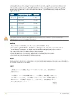
Color/State
Meaning
Off
Device powered off, or radio disabled
Green- solid
Radio enabled in access (AP) mode
Green- flashing off
Radio enabled in uplink or mesh mode
Amber- solid
Radio enabled in monitor or spectrum analysis mode
Table 2:
Radio Status LED
LED Display Settings
The LEDs have three operating modes that can be selected in the system management software:
n
Default mode: refer to
and
.
n
Off mode: all LEDs are off
n
Blink mode: all LEDs blink green (synchronized)
To force the LEDs into off mode or back to software defined mode, press the reset button for a short duration
(less than 10 seconds).
Bluetooth Low Energy Radios
650 Series access points are equipped with an integrated BLE and 802.15.4 radio that provide the following
capabilities:
n
location and asset-tracking applications
n
wireless console access
n
IoT gateway applications
Console Port
The console port is a Micro-B connector is located on the back of this device. Use the proprietary AP-CBL-SERU
cable or AP-MOD-SERU module (sold separately) for direct management of this device when connected to a
serial terminal or laptop. For pin-out details, refer to
.
Figure 4
Micro-B Port Pin-out
1: NC
2: RXD
3: TXD
4: GND
5: GND
Ethernet Ports
The 650 Series Campusaccess points are equipped with two 100/1000/2500/5000 Base-T auto-sensing
MDI/MDX wired RJ45 Ethernet ports (E0 and E1). The 2.5bps speed complies with NBase-T and 802.3bz
specifications. Both ports are compliant with 802.3ab 1000Base-T Gigabit Ethernet and 802.3az (Energy
Efficient Ethernet) standards. Both ports support 802.3af, 802.3at and 802.3bt Power over Ethernet
compliance to accept power from a POE source, such as a PoE midspan injector, or a network switch.
The 650 Series access points are equipped with two active Ethernet ports (Eth0 and Eth1) (link to figure). Both
ports are 100/1000/2500/5000 Base-T, auto-sensing MDI/MDX, which supports uplink connectivity when
linked by an Ethernet cable. Refer to
for a detailed port pin-out.
Rev 01 | October 2021
|
3

