4
|
Rev 01|October 2021
Figure 5
Ethernet Port Pin-Out
1000Base-T Gigabit
Ethernet Port
RJ-45 Female
Pin-Out
1
2
3
4
5
6
7
8
Spare Pair
Spare Pair
Spare Pair
Spare Pair
ETH Rx+
ETH Rx-
ETH Tx+
ETH Tx-
(POE positive)
(POE positive)
(POE negative)
(POE negative)
(POE negative)
(POE negative)
(POE positive)
(POE positive)
The 650 Seriesaccess points are equipped with two Ethernet ports (E0 and E1):
n
E0 port: 100/1000/2500Base-T auto-sensing MDI/MDX wired RJ45 network connectivity port
n
E1 port: 100/1000Base-T auto-sensing MDI/MDX wired RJ45 network connectivity port
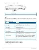
Kensington Lock Slot
The 650 Series is equipped with a Kensington lock slot for additional physical security.
USB Interface
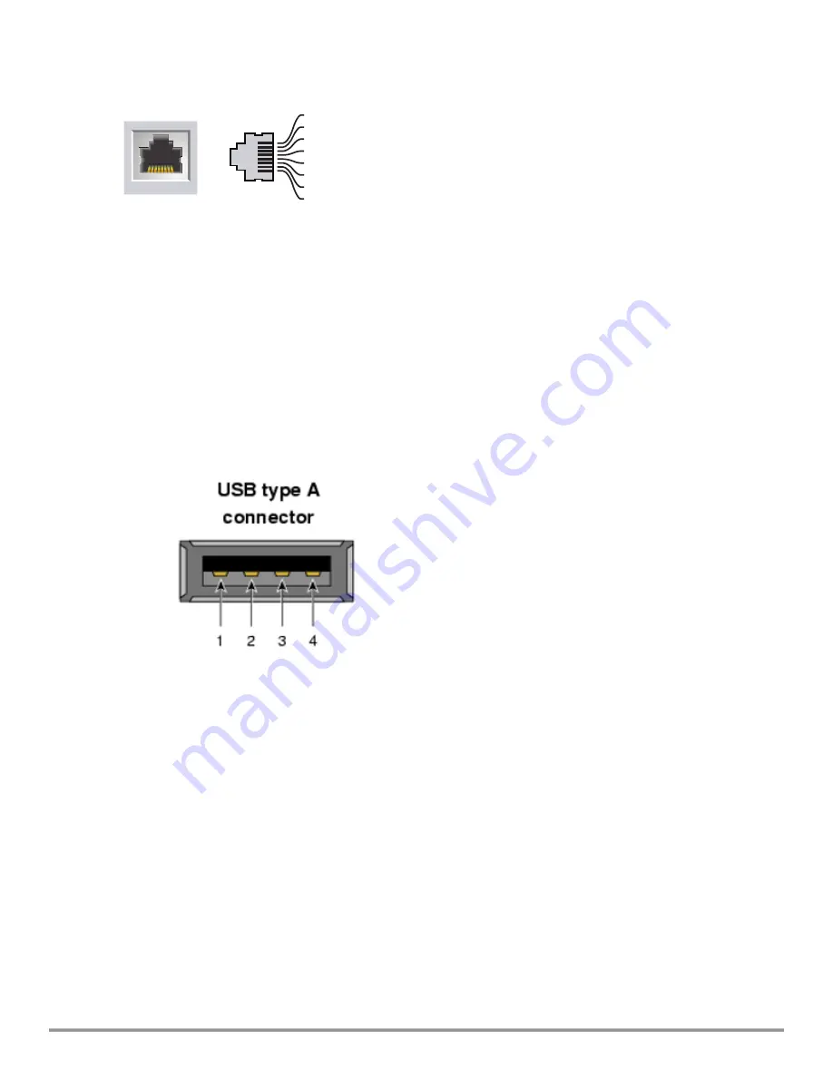
The USB 2.0 interface located on the top of the is 650 Series compatible with selected cellular modems and
other peripherals. When active, this port can supply up to 5W/1A to a connected device.
Figure 6
650 Series USB
Reset Button
The reset button located on the bottom of the device can be used to reset the access point to factory default
settings or turn off/on the LED display.
Use one of the following methods to reset the access point to factory default settings:
n
To reset during normal operation:
l
Hold the reset button for more than 10 seconds while the access point is running.
l
Release the reset button.
n
To reset during power up, hold the reset button while the access point is powering up.
The system status LED will flash again within 15 seconds indicating that the reset is completed. The access
point will now continue to boot with the factory default settings.
To toggle the LED display between Off and Blinking, during the normal operation of the access point, shortly
press and release the reset button using a small, narrow object, such as a paperclip.

