background image

GETTING STARTED

1.3


I/O connectors

1.3.1


Video sources

The 

picasso

TM


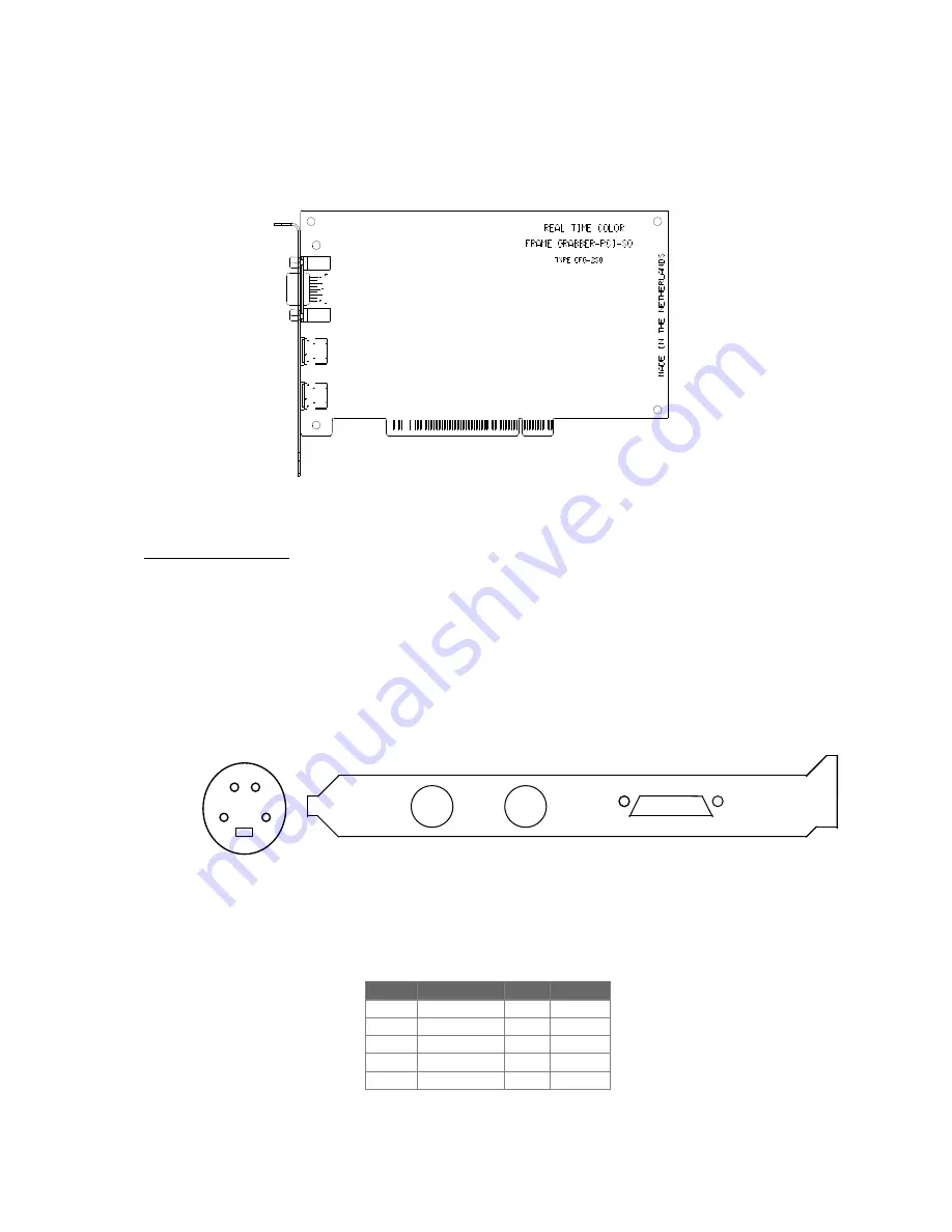
supports up to four video sources. The video input-connectors VID0 and VID1

are 4-pins minidin female connectors [see Figure 2].

n


Composite video sources (CVBS) are connected to input A-D of VID0 and VID1
[see Table 1].

n


S-video (S-VHS or Hi8) is connected to VID0 and VID1. Inputs A and C are used for the Y
(luminance) channel of the S-video source. Inputs B and D are used for the C (chrominance)
channel of the S-video source [see Table 2].

Sub D-

VID1

VID0

Figure 1

         VID0

     VID1

 Sub D-9


3        4

         1              2 

Figure 2: Close-up of VID0 and VID1.

Input

Connector

Pins

mode

A

VID 0

3

mode 0

B

VID 0

4

mode 5

C

VID 1

3

mode 2

D

VID 1

4

mode 1

GND

VID0,VID1

1, 2

Table 1: Connecting Composite Video to the picasso

TM

.

Summary of Contents for PICASSO PCI-2SQ

Page 1: ...PICASSOTM PCI 2SQ PCI color frame grabber User Manual Draft version Rev C doc 2 1 ...

Page 2: ... Engineering BV is believed to be accurate and reliable however no responsibility is assumed by ARVOO Engineering BV for its use nor for any infringements of patents or other rights of third parties which may result from its use No license is granted by implication or otherwise under any patent rights of ARVOO Engineering BV PicassoTM is a trademark of ARVOO Benelux BV PentiumTM is a registered tr...

Page 3: ...ONTENTS 1 GETTING STARTED 6 1 1 HARDWARE AND SOFTWARE REQUIREMENTS 6 1 2 INSTALLING THE PICASSO TM 6 1 3 I O CONNECTORS 6 1 3 1 Video sources 7 1 3 2 General Purpose Input Output connector 9 2 OPERATION PRINCIPLES 11 2 1 FUNCTIONAL OVERVIEW 11 ...

Page 4: ...sing or full frame display of real time video in a window maximum 30 frames sec The picassoTM PCI 2SQ operates as a PCI bus master allowing it to transfer images directly to the system memory or the VGA memory without impacting the processor The picassoTM PCI 2SQ has four composite video inputs or two S video inputs that are software controlled and accept NTSC PAL or SECAM video signals ...

Page 5: ... 60 Hz n RS 170 CCIR 601 level compatible n Square pixel 1 1 aspect ratio n Automatic or programmable gain control n Real time scaling Useful for reducing the size of images on the display Images can be scaled down randomly n Memory Memory Management Unit MMU supports Virtual Memory up to 4 Mbytes DMA channel The picasso TM has 3 DMA channels n Data Formats Data can be stored in several RGB format...

Page 6: ... Installing the picassoTM 1 Select a 32 bit PCI bus master expansion slot Refer to your computer systems user manual to determine which slots are bus masters 2 Remove the metal bracket 3 Before handling the board discharge any static build up on your body by touching the metal case of the computer Remove the board from its bag and hold the picassoTM by its top edges and do not touch its components...

Page 7: ... Table 1 n S video S VHS or Hi8 is connected to VID0 and VID1 Inputs A and C are used for the Y luminance channel of the S video source Inputs B and D are used for the C chrominance channel of the S video source see Table 2 Sub D VID1 VID0 Figure 1 VID0 VID1 Sub D 9 3 4 1 2 Figure 2 Close up of VID0 and VID1 Input Connector Pins mode A VID 0 3 mode 0 B VID 0 4 mode 5 C VID 1 3 mode 2 D VID 1 4 mod...

Page 8: ...at one time ATTENTION When you use the delivered cable with the frame grabber then the RED cinch plug phono connector is connected to pin 3 of the VID 0 1 minidin and the BLACK cinch plug is connected to pin 4 Cam Cam Cam Cam A B C 3 4 3 4 VID0 VID1 D Figure 3 3 4 3 4 VID0 VID1 Cam Cam Y and C Y and C Figure 4 Input S video Pins Mode VID0 3 luminantie 4 chrominantie Mode 6 VID1 3 luminantie 4 chro...

Page 9: ...an external 5 V power supply The maximum voltage is 5 5 V and the input current is 10 mA ATTENTION The maximum output current is 100mA The outputs are open drain which means that logic 1 will force the output to ground A wiring example to connect an output is given below ATTENTION When the computer is turned off and the external power supply stays up the output will also be forced to ground Sub D ...

Page 10: ...ng example for an output is given In Figure 7 a wiring example for an input is given External 5V External power supply GND picasso TM PC Input 0 1 Figure 7 output 0 1 External 5V Imax 100 External power supply GND picasso TM PC Figure 6 ...

Page 11: ...dge The images can be scaled down randomly By specifying starting pixel line locations and size an exact region can be selected The user has to specify both the source and target fields The scaler controls also brightness contrast hue and saturation The data can be stored in different RGB output formats V synch YUV Scaler bright contrast hue Frontend an alo g digitizer 2Y C or 4CVBS 2 inputs and 2...

Page 12: ...d only and must be driven by an external source It is possible to generate interrupts from the inputs The output register is read write PCI interface The scaled image is transferred directly to the system memory or the displays frame buffer under program control ...

Page 13: ...pical Max Supply voltage Vcc 4 75 V 5 0 V 5 25 V Supply current Vcc 5 0 V 800 mA Supply voltage 12Vcc 11 5 V 12 0 V 12 5 V Supply current 12Vcc 75 mA General purpose voltage 4 5 V 5 0 V 5 5 V Input current Vgp 5 0 V 10 mA Output current Vgp 5 0 V 80 mA 100 mA Vi p p CVBS input signal 0 5 V 1 0 V 1 38 V Zi input impedance 75Ω Table 4 Environmental Operating temperature 0º to 70º Celsius Storage tem...

Reviews: