background image

GETTING STARTED

picasso

TM 


PCI-3C

User Manual

- 8 -

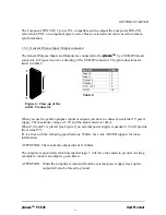
The video input-connector is a SUB-D15 connector and the GPIO is a SUB-D9 connector [see
Figure 2].

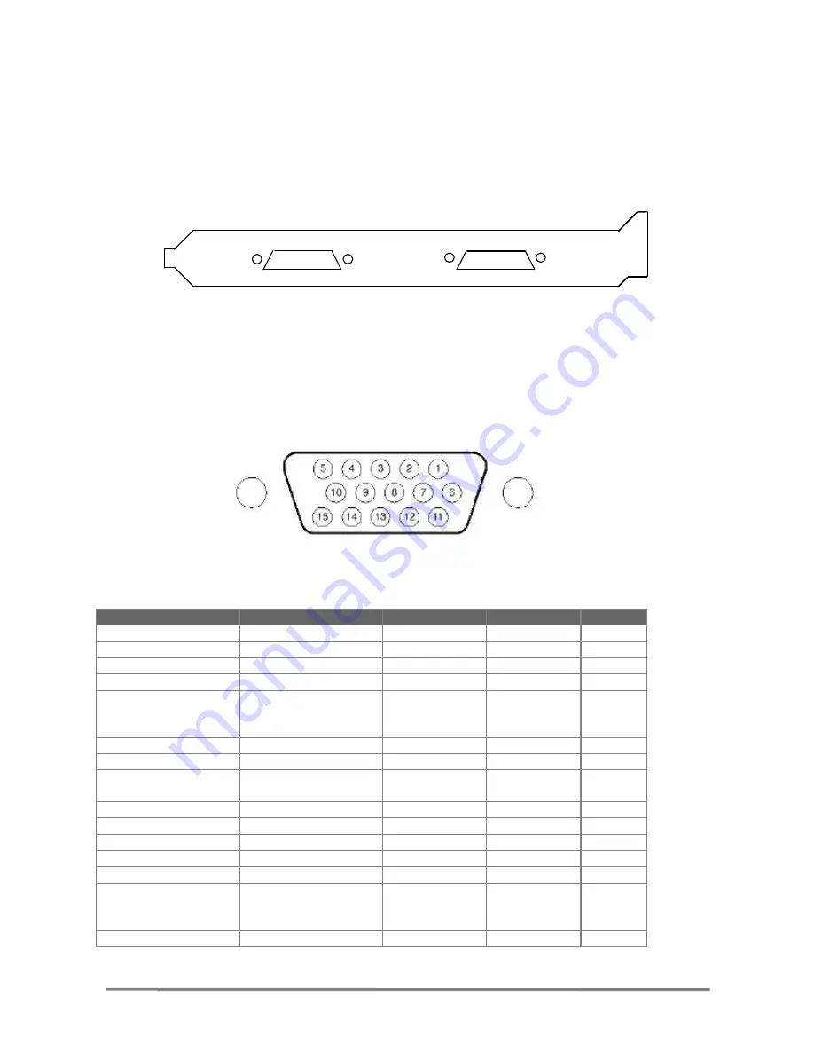
Table 1 shows connection of the video sources to the SUB-D15 connector. The pin assignment
depends on the video sources that are used. Four modes can be distinguished: (1) RGB mode for
3 component video, e.g. RGB or YUV. (2) Y-mode for B&W video. (3) CVBS-mode for CVBS
composite video. (4) S-video-mode for S-video (Y/C) video.

       SUB-D15


          SUB-D9


Figure 2: Close-up of RGB-VID and GPIO connectors.

Figure 3: Close-up of the SUB-D15 female connector

RGB-mode

Y-mode

CVBS-mode

S-video

Pins

R1

Y1

NOT USED

NOT USED

1

G1

Y2

NOT USED

NOT USED

2

B1

Y3

NOT USED

NOT USED

3

GND

GND

GND

GND

4

Composite sync input

for camera 1

 (ana1og or TTL level)

Composite sync input

for Y1,Y2 or Y3

(ana1og or TTL level)

NOT USED

NOT USED

5

GND

GND

GND

GND

6

NC

NC

NC

NC

7

Composite sync output /

External sync input

Composite sync output /

External sync input

NOT USED

NOT USED

8

NC

NC

NC

NC

9

GND

GND

GND

GND

10

R2

Y4

C1 input

Y1

11

G2

Y5

C2 input

Y2

12

B2

Y6

C3 input

C1

13

Composite sync input

for camera 2

 (ana1og or TTL level)

Composite sync input

for Y4,Y5 or Y6

(ana1og or TTL level)

C4 input

C2

14

GND

GND

GND

GND

15

Table 1 SUB-D15

Summary of Contents for PICASSO PCI-3C PRO

Page 1: ...PICASSOTM PCI 3C PRO Dual input Triple channel Analog Video PCI frame grabber with optional CVBS inputs User Manual Draft version Rev 2 B doc 1 0...

Page 2: ...Engineering BV is believed to be accurate and reliable however no responsibility is assumed by ARVOO Engineering BV for its use nor for any infringements of patents or other rights of third parties w...

Page 3: ...ser Manual 3 CONTENTS OVERVIEW 4 FEATURES 5 1 GETTING STARTED 6 1 1 HARDWARE REQUIREMENTS 6 1 2 INSTALLING THE PICASSO TM 6 1 3 I O CONNECTORS 7 1 3 1 Video sources 7 1 3 2 General Purpose Input Outpu...

Page 4: ...cting the processor The picassoTM PCI 3C has two analog RGB inputs with separate sync inputs Sync is also accepted on one of the color inputs The video input is software controlled and accepts both st...

Page 5: ...at with 768 640 active pixels resolution per frame NTSC PAL SECAM interlaced or progressive scan The maximum sample frequency is 20MHz n RS 170 CCIR 601 level compatible n Square pixel 1 1 aspect rati...

Page 6: ...he Intel 440BX i810 i815 or i820 chipsets 1 2 Installing the picassoTM 1 Select a 32 bit PCI bus master expansion slot Refer to your computer systems user manual to determine which slots are bus maste...

Page 7: ...the frame grabber on an incoming video signal When the green LED is flashing it indicates an error condition Video input signal doesn t contain sync timing Wrong selection of video standard PAL inste...

Page 8: ...tors Figure 3 Close up of the SUB D15 female connector RGB mode Y mode CVBS mode S video Pins R1 Y1 NOT USED NOT USED 1 G1 Y2 NOT USED NOT USED 2 B1 Y3 NOT USED NOT USED 3 GND GND GND GND 4 Composite...

Page 9: ...connect an external 5V power supply The maximum voltage is 5 5V and the input current is 10mA When U19 and F1 is placed see Figure 1 no external power supply is needed U19 will provide the external 5V...

Page 10: ...Figure 6 a wiring example for an output is given In Figure 6 a wiring example for an input is given External 5V External power supply GND picasso TM PC Input 0 1 Figure 6 output 0 1 External 5V Imax 1...

Page 11: ...Vcc 4 75 V 5 0 V 5 25 V Supply current Vcc 5 0 V 1 0 A 1 1 A Supply voltage 12Vcc 11 5 V 12 V 12 5 V Supply current 12Vcc 110 mA 125 mA Supply voltage 12Vcc 11 5 V 12 V 12 5 V Supply current 12Vcc 50...

Reviews: