U.S and Foreign Patents & patents pending
© Copyright 2004 by Arzel
®
Zoning Technology, Inc.
4
Rev 2.1.5
Quick Start Instructions
The Arzel
®
Zoning Zonocity™ Zoning Systems™ are easy to install. Please read these instructions
completely to ensure that you understand the system.
Pay special attention to the Control Panel
Section on Page 2.
This QuickStart page has been provided as an installation overveiw with
references to more detailed information other places in this manual.
1 Install Dampers/Run
Tubing
Dampers install directly into existing
trunk. Dampers install with the tubing
port pointing toward the
equipment. Install one tubing run for
each zone. Use a tee for multiple
dampers on one zone. Arzel
®
recommends using a different color
tube for each zone
.
5 Connect Transformer
Use 18 gauge - 2 conductor solid wire to connect R and C on the Power Terminal Strip to the mounting screws on the
40VAC self-resetting, plug-in transformer supplied with the Arzel
®
Zoning System. Plug in the transformer to any
standard 120VAC receptacle.
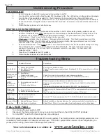
6 Test the System
See commissioning procedure on pg. 8.
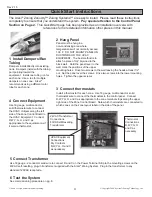
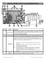
3 Connect thermostats
Install a thermostat for each zone. Use 18 gauge, multiconductor, solid
thermostat wire to connect the thermostats to the control panel. Connect
R,W,Y,G,O, and C as appropriate to the zone terminal strips along the upper
right side of the Zone Control Board. Note which thermostats are connected to
which zones on the zone layout label on the side of the panel.
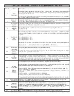
4 Connect Equipment
Use 18 gauge, multiconductor,
solid thermostat wire to connect
the HVAC Outputs along the left
side of the Zone Control Board to
the HVAC Equipment. Connect
R,W,Y,G, O, and C as
appropriate to the equipment as if
it were a thermostat.
2 Hang Panel
Panel must be hung in a
non-condensing area where
temperatures will not normally exceed
100
o
F. DO NOT MOUNT PANEL ON
DUCTWORK OR THE HVAC
EQUIPMENT. The best method is to
attach a piece of 3/4” plywood to the
block wall. Hold the panel level to the
wall, mark the positions of the upper
mounting holes. Drive two screws to the wall leaving the heads at least 1/2”
out. Set the panel over the screws. Drive two screws into the lower mounting
holes. Tighten the upper screws.
Thermostat
Connections
R,W,Y,G, O
and C as
necessary
HVAC Equipment
Connections
Dry Contacts
R,W,Y,G, O and C
as necessary
24VAC Transformer
Connections
40VA Self-Resetting
Transformer


