background image

U.S and Foreign Patents & patents pending

   © Copyright 2004 by Arzel

®

 Zoning Technology, Inc.

5

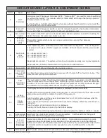
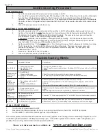
WIRING DIAGRAMS

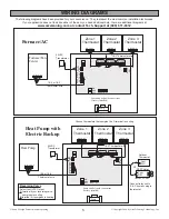
The following diagrams have been provided for your convenience.  They represent the most common installation techniques.

If your application does not look like either of these or you need additional help, there are additional diagrams at

www.arzelzoning.com or contact Tech. Support at (800) 611-8312.

Pump

Pump and Solenoid connections
(factory installed)

Zone 1          Zone 2          Zone 3

R   W  Y G  O B  C

HVAC Outputs

 24VAC    R C

Remote   ODT

Pump  1  2  3  +

ON
MPS
OFF

24VAC
Transformer

Furnace/Fan
Center

R  W  Y G O  C

  18-4 or 18-5
Thermostat wire

Zone 1

Thermostat

R W Y G O C

Zone 2

Thermostat

Zone 3

Thermostat

Pump

Pump and Solenoid connections
(factory installed)

Zone 1          Zone 2           Zone 3

R   W  Y G  O B  C

HVAC Outputs

 24VAC    R C

Remote   ODT

Pump  1  2  3  +

ON
MPS
OFF

24VAC
Transformer

Heat Pump

R  W  Y G O  C

  18-5 or 18-6
Thermostat wire

Zone 1

Thermostat

Zone 2

Thermostat

Zone 3

Thermostat

Reversing Valve

Select the HVAC Output

O

 terminal if your reversing valve

    energizes in cooling,

B

 terminal if it energizes in heating

Choose thermostats that energize the O terminal in cooling

18-5 Thermostat wire

Outdoor

Thermostat

Com
N/O

or

SPST Relay

Com
N/O

Load side   Coil side

Connect relay coil to
E & C from any single
thermostat

Furnace/AC

Heat Pump with
Electric Backup

18-5 Thermostat wire

E
C

R W Y G O C

R W Y G O C

R W Y G O C

R W Y G O C

R W Y G O C

R W Y G O C

R W Y G O C

R W Y G O C

R W Y G O C

R W Y G O C

R W Y G O C
Summary of Contents for Zonocity

Page 1: ...nology Inc 1 Installation Instructions For Comfort Reliability and Easy Installation Arzel Zoning Technology Inc 4801 Commerce Pkwy Cleveland OH 44128 Ph 216 831 6068 or Toll Free 800 611 8312 Fax 216...

Page 2: ...nel contains both AC and DC Terminals See Equipment Notes pp 6 and 7 for more details 11 Leave these instructions with installed system for future use 1 The Arzel Zoning System uses a self contained l...

Page 3: ...gize the solenoid valve s for non calling zone s and make the appropriate dry contact relays to start the HVAC equipment 2 3 1 Dampers open with vacuum Dampers close with pressure The logic board is d...

Page 4: ...ect thermostats Install a thermostat for each zone Use 18 gauge multiconductor solid thermostat wire to connect the thermostats to the control panel Connect R W Y G O and C as appropriate to the zone...

Page 5: ...G O C Zone 2 Thermostat Zone 3 Thermostat Pump Pump and Solenoid connections factory installed Zone 1 Zone 2 Zone 3 R W Y G O B C HVAC Outputs 24VAC R C Remote ODT Pump 1 2 3 ON MPS OFF 24VAC Transfo...

Page 6: ...h t s i t i u c r i c t u p t u O C A V H e h T l o r t n o C e n o Z e h t y b d e l l a c y l p p u s r e w o p t a t s o m r e h t d n a l o r t n o C e n o Z e h t m o r f R W Y G B O C s i h t o...

Page 7: ...i T e d i r r e v O o t d r a o b C P e h t n o d e d i v o r p s i O D T h c t i w s e d i r r e v O y a l e D e m i T t c a t n o c y r a t n e m o m s i h T t c e n n o c s i d t s u m u o y h c t...

Page 8: ...t n o c t n e m p i u q e r e m r o f s n a r t l e n a p n i s l a n i m r e t t u p t u O C A V H f o C o t t n e m p i u q e m o r f C t c e n n o C w o l f r i a w o L s e n o z o t n e p O r e p...

Reviews: