Asahi Seiko (Europe) Ltd
Product Information
SH-400F Technical Information
Page 6
Issue 1 September 2000
3.0 OPERATION AND MAINTENANCE
The chassis mounting plate for the motor/gearbox assembly and coin disc is inclined
at 30º to the horizontal.
A disc with holes set slightly larger than the coin diameter rotates in a clockwise
direction collecting coins from the base of the hopper and moving them towards the
payout point at the top of the mounting plate.
When the coin held in the disc approaches the payout point, two spring-loaded pins in
the base deflect it sideways beneath the bowl allowing it to be dispensed between two
rollers, one of which is spring-loaded. The coin then passes out through the sensor
which provides pulses of between 10ms and 30ms in duration (dependent upon coin
diameter).
When the control signal is removed (see Section 4.4.1), the motor is stopped instantly
by the DC motor brake. The motor brake briefly applies reverse current to prevent
overrun, ensuring accurate coin dispensing.
3.1
Removing/Replacing the Hopper Bowl
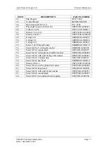
To remove the bowl, depress the bowl lock pin (part 37) located below the
lower edge of the bowl and turn the bowl clockwise. Lift the bowl clear of the
retaining pins.
Replacement is the reverse of the removal operation.
3.2
Removing/Replacing the Coin Disc
With the hopper bowl detached, remove the large domed head screw (part 61)
in the centre of the disc. The disc (part 22) can now be lifted off and adjusted
to suit a different coin diameter if required.
Note:
When adjusting the coin disc for change of coin diameter it may be
necessary to adjust other clearances. Refer to Section 5 on hopper
calibration.


