11
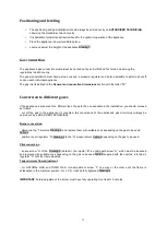
Positioning and leveling
The positioning and gas installation should always be carried out by an
AUTHORISED TECHNICIAN
,
observing the standards of each country.
It is advisable to install an extraction hood for the optimum operation of the appliance.
Place the appliance in a well ventilated place.
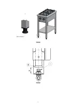
Level and adjust the height of the appliance Drawing 1.
Gas connection
The appliance's gas connection must always be carried out by an Authorized Technician, observing the
regulations in each country.
The general installation must have a stop-cock and a pressure regulator and it also advisable to install a shut-off
cock on each individual appliance.
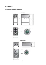
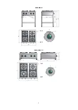
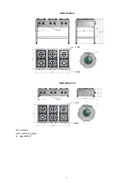
The gas inlet is defined in the
General and connection dimensions
section with the letter
“G”
.
Conversion to different gases
If the appliance is prepared for a different type of gas to the one available in the installation, you should proceed
as follows:
- cut off the gas to the appliance if connected. (All conversions of the appliance's gas circuit must always be
carried out by a QUALIFIED TECHNICIAN).
Burner conversion
- d
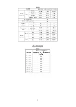
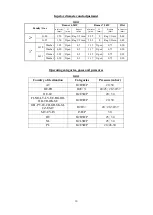
ismantle the “I” injectors Drawing 2, and replace them with suitable ones depending on the gas to be used
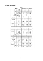
Table 3
- p
osition the air regulator “R” Drawing 2 to the “H” measurement Table 3 depending on the gas to be used.
Pilot conversion
- l
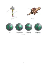
oosen screw “A” of the Drawing 3 (detail A), the injector “B” is underneath screw “A”, which must be loosened
and replaced with suitable ones depending on the gas to be used Table 3 supplied with the nozzles; turn the air
regulat
or “C” until the flame steadies.
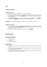
Taps minimum flow adjustment
- f
or NATURAL GAS and TOWN GAS, turn adjustment screw “F” one way or the other until the flame is
established in the minimum position. For L.P.G. it will be fully tightened Drawing 4
IMPORTANT
: before adjustment, the burner must have fully operating for at least 15 minutes.
Summary of Contents for GRE-1200-24
Page 4: ...4 GRE 800 13 GRE 800 13 T 7 7kW 4 8kW 7 7kW 4 8kW ...
Page 5: ...5 GRE 1200 24 GRE 1200 24 T W pointer VM table tap valve G gas inlet 7 7kW 4 8kW 7 7kW 4 8kW ...
Page 6: ...6 Drawing 1 Drawing 2 REGULATED LEGS ...
Page 7: ...7 Drawing 3 Drawing 4 1 OFF 2 PILOT POSITION 3 MAXIMUM 4 MINIMUM Drawing 5 C B A F ...

