background image

12 


USE 

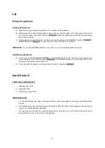
Using the appliance 

Turning the burners on. 

a)  Open the main general gas-tap installed on the outside of the appliance.  

b)  Lightly  press  the  control  corresponding  to  the  burner  you  want  to  ignite  until  it  becomes  unlocked  and 

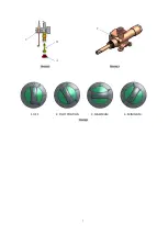
turn it anticlockwise to the PILOT position (Drawing 5), press this position again and light the pilot with a 
flame until it is stable. 

c)  Then onwards, to ignite the burner, turn the control anticlockwise to the MAXIMUM position (Drawing 5). 

MINIMUM position (Drawing 5). Loosen the control when this position is reached. 


IMPORTANT

: To go to the MAXIMUM position or any other one, you must always press the control. 


Switching the burners off. 

a)  If  it  is  in  any  of  the  MAXIMUM,  MINIMUM  or  intermediate  positions,  the  control  must  be  pressed  and 

turned clockwise to the PILOT position (Drawing 5) and then stop pressing it. In this position, the burner 
will switch off, and the pilot will remain on. 

b)  To turn the pilot off, press the control and turn it to the OFF position (Drawing 5). 


MAINTENANCE


FUNCTIONAL COMPONENTS. 

1.  Table tap-

valve “VM”  

2. 

Table pilot “PM”  

3. 

Table thermocouple “TM”  


IMPORTANT NOTE: 


It is vital that the flue pipe does not become blocked, not even partially, for the proper functioning of the 
burners. 


The replacement of any functional component that can affect the safety of the appliance must be carried 
out by an AUTHORISED TECHNICIAN. 


As a general rule, whenever an operating component is replaced, you


must check that the mains tap is 

shut and that is no fire in the vicinity of the appliance. 


Summary of Contents for GRE-1200-24

Page 1: ...aintenance GAS RANGES Models GRE 400 20 GRE 400 11 GRE 400 02 GRE 800 31 GRE 800 22 GRE 800 13 GRE 1200 42 GRE 1200 33 GRE 1200 24 GRE 400 20 T GRE 400 11 T GRE 400 02 T GRE 800 31 T GRE 800 22 T GRE 800 13 T GRE 1200 42 T GRE 1200 33 T GRE 1200 24 T ...

Page 2: ...eplaced pages full of writing Nevertheless we recommend you thoroughly read this manual complied by ASBER s kitchen supervisors in order to benefit to the maximum from the multiple possibilities and advantages this appliance offers you Keep this manual near to the appliance and at all times in an accessible place ASBER INDEX INSTALATION 3 General and connection dimensions 3 Technical specification...

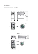
Page 3: ...3 INSTALATION General and connection dimensions GRE 400 11 GRE 400 11 T 7 7kW 4 8kW 7 7kW 4 8kW ...

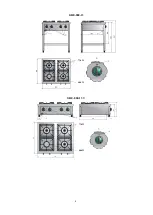
Page 4: ...4 GRE 800 13 GRE 800 13 T 7 7kW 4 8kW 7 7kW 4 8kW ...

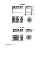
Page 5: ...5 GRE 1200 24 GRE 1200 24 T W pointer VM table tap valve G gas inlet 7 7kW 4 8kW 7 7kW 4 8kW ...

Page 6: ...6 Drawing 1 Drawing 2 REGULATED LEGS ...

Page 7: ...7 Drawing 3 Drawing 4 1 OFF 2 PILOT POSITION 3 MAXIMUM 4 MINIMUM Drawing 5 C B A F ...

Page 8: ...al consumptions m3 h G20 1 016 1 323 1 630 G25 1 108 1 490 1 871 kg h G30 0 799 1 040 1 282 G31 0 787 1 025 1 263 Table 1B Model GRE 800 31 GRE 800 22 GRE 800 13 External dimension mm Width 800 800 800 Depth 700 700 700 Height 850 850 850 Height T model 280 280 280 NET WEIGHT kg 50 NET WEIGHT T model kg 43 Numbers of burners 4 5 kW 3 2 1 7 5 kW 1 2 3 Power Output kW h G 20 G 30 G 31 22 1 25 27 9 G...

Page 9: ...s 4 5 kW 4 3 2 7 5 kW 2 3 4 Power Output kW h G 20 G 30 G 31 34 6 37 5 40 4 G 25 33 2 36 3 39 4 Nominal consumptions m3 h G20 3 661 3 968 4 275 G25 4 087 4 469 4 851 kg h G30 2 880 3 121 3 363 G31 2 837 3 074 3 312 Air consumption Table 2 Model Air consumption necessary for combustion Nm3 h GRE 400 20 10 GRE 400 11 12 GRE 400 02 15 GRE 800 31 21 GRE 800 22 24 GRE 800 13 27 GRE 1200 42 33 GRE 1200 ...

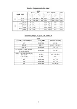
Page 10: ...pen 0 5 1 35 Open 0 75 0 20 50mbar 0 90 Open 0 5 1 17 Open 0 75 0 20 G 31 37mbar 1 05 Open 0 5 1 35 Open 0 75 0 20 50mbar 0 90 Open 0 5 1 17 Open 0 75 0 20 Operating categories gases and pressures Table 4 Country of destination Categories Pressure mbar AT II2H3B P 20 50 BE FR II2E 3 20 25 28 30 37 DE LU II2E3B P 20 50 FI NO LT LV EE BG RO HR TR DK SE II2H3B P 20 30 GB PT IE CH GR SK SI CZ ES IT II...

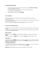
Page 11: ...pe of gas to the one available in the installation you should proceed as follows cut off the gas to the appliance if connected All conversions of the appliance s gas circuit must always be carried out by a QUALIFIED TECHNICIAN Burner conversion dismantle the I injectors Drawing 2 and replace them with suitable ones depending on the gas to be used Table 3 position the air regulator R Drawing 2 to t...

Page 12: ...ff a If it is in any of the MAXIMUM MINIMUM or intermediate positions the control must be pressed and turned clockwise to the PILOT position Drawing 5 and then stop pressing it In this position the burner will switch off and the pilot will remain on b To turn the pilot off press the control and turn it to the OFF position Drawing 5 MAINTENANCE FUNCTIONAL COMPONENTS 1 Table tap valve VM 2 Table pil...

Page 13: ...on the symbol the materials can be recycled By recycling and other ways of processing electrical waste and electronic equipment you can significantly contribute to protecting the environment Contact your local authorities for more information of the nearest collection point To conserve the environment at the end of the useful life of your product leave it in the appropriate places in accordance wi...

Reviews: