8 Inductors
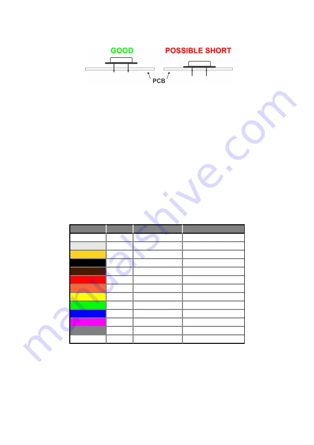
Inductors are soldered just like resistors. They also use similar
color-coding, usually with four bands. The first two are the
base value (see table below), the third is the multiplier to the
base value and the fourth is the tolerance. The inductor value
is:
base value * multiplier [
± tolerance ]
Color Codes:
Color
Digit
Multiplier
Tolerance
±
in %
None
-
-
20
Silver
-
10
-2
10
Gold
-
10
-1
5
Black
0
10
0
-
Brown
1
10
1
1
Red
2
10
2
2
Orange
3
10
3
-
Yellow
4
10
4
-
Green
5
10
5
0.5
Blue
6
10
6
-
Purple
7
10
7
-
Grey
8
10
8
-
White
9
10
9
-
12
Summary of Contents for AE20401
Page 23: ...Finished Component Side Finished Solder Side without the LCD LCD Mounting 17 ...
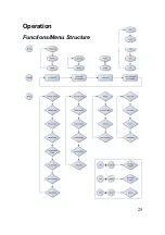
Page 31: ...Operation Functions Menu Structure 25 ...
Page 37: ...31 Example 1 noise Example 2 one signal superimposed on another ...
Page 50: ...Circuit Diagram Part 1 2 44 ...
Page 51: ...Part 2 2 45 ...
Page 63: ... Nr of valid counts depends on range 57 ...
Page 64: ...ASCEL ELECTRONIC www ascel electronic de 2015 ...


