Installation of the modules
Channel B / PWR (Power Meter)
The modules are fully assembled and tested, they just have to
be put on the appropriate pin header. The position of the socket
is such that each module only fits on the correct header. Be
careful not to put the module a row or column aside on the
header - it may be damaged if the power is turned on then!
The modules may be used with a case only!
If the original optional case is not used, the unit must be
enclosed in another suitable case. The SMA input jacks must be
tightly screwed to the front panel with the two provided nuts,
before any cables may be connected! The pin header and
socket must not be exposed to mechanical stress.
1ppm TCXO Oscillator Module
The oscillator module is soldered in instead of the standard
crystal oscillator, its size and pinout is identical.
16
Summary of Contents for AE20401
Page 23: ...Finished Component Side Finished Solder Side without the LCD LCD Mounting 17 ...
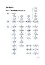
Page 31: ...Operation Functions Menu Structure 25 ...
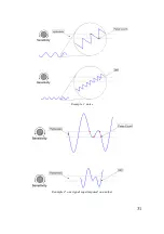
Page 37: ...31 Example 1 noise Example 2 one signal superimposed on another ...
Page 50: ...Circuit Diagram Part 1 2 44 ...
Page 51: ...Part 2 2 45 ...
Page 63: ... Nr of valid counts depends on range 57 ...
Page 64: ...ASCEL ELECTRONIC www ascel electronic de 2015 ...


