Troubleshooting Checklist
Check and tick off every step.
□
Is the polarity of the supply voltage correct?
□
Is the supply voltage in the range of 8-12V when the
device is turned on?
□
Are all resistors placed right? Check the color bands.
□
Are the polarities of the diodes correct? The cathode
band must match the bar on the silkscreen symbol.
□
Verify the polarity of the electrolytic capacitors. Keep
in mind that the marking on the capacitor can point to
the (+) or (-) lead. The actual meaning is printed inside
the marking.
□
Are all ICs in the right place and with correct
orientation?
□
Are all IC leads plugged inside the socket? They can
bend and stay outside easily.
□
Measure the resistance between the power supply input
terminals and between the regulated 5V rail and ground
- they must not be shorted.
20
Summary of Contents for AE20401
Page 23: ...Finished Component Side Finished Solder Side without the LCD LCD Mounting 17 ...
Page 31: ...Operation Functions Menu Structure 25 ...
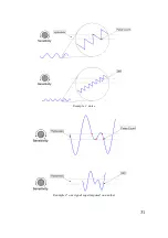
Page 37: ...31 Example 1 noise Example 2 one signal superimposed on another ...
Page 50: ...Circuit Diagram Part 1 2 44 ...
Page 51: ...Part 2 2 45 ...
Page 63: ... Nr of valid counts depends on range 57 ...
Page 64: ...ASCEL ELECTRONIC www ascel electronic de 2015 ...


