Basic Operation
General Notes
Signals may only be connected to one of the inputs or the EXT
jack if the device is powered on!
If a signal is applied and the
device is off, damage to the input circuitry may occur, even if the
signal is within the allowed limits for the particular input! Always
disconnect all cables before switching the counter off.
Do not exceed the allowed maximum input voltage/power!
Doing so will damage the input circuitry!
If no signal is connected to Channel A (also Channel B with high
electric field strength), still a frequency may be indicated. This is
not a fault, but the result of the inputs high sensitivity and the
relatively high input impedance of 1 MΩ. Electric fields from the
mains (50/60 Hz), WLAN, cordless phones et al. induce a voltage
to the input, which is then amplified and counted. It is the same
effect that let a digital multimeter with 10 MΩ input impedance
always show a small voltage, when not connected to any source -
here you can see the frequency of this voltage instead.
Ensure that the test leads used are suitable for the particular
frequency. Correct measurements in the GHz range require all
involved components (test leads, adapters, attenuators...) to be
suitable for the test frequency. E.g., the widely used RG58 coaxial
cable is not suitable for high frequencies!
26
Summary of Contents for AE20401
Page 23: ...Finished Component Side Finished Solder Side without the LCD LCD Mounting 17 ...
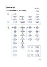
Page 31: ...Operation Functions Menu Structure 25 ...
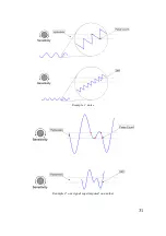
Page 37: ...31 Example 1 noise Example 2 one signal superimposed on another ...
Page 50: ...Circuit Diagram Part 1 2 44 ...
Page 51: ...Part 2 2 45 ...
Page 63: ... Nr of valid counts depends on range 57 ...
Page 64: ...ASCEL ELECTRONIC www ascel electronic de 2015 ...


