40
2.
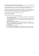
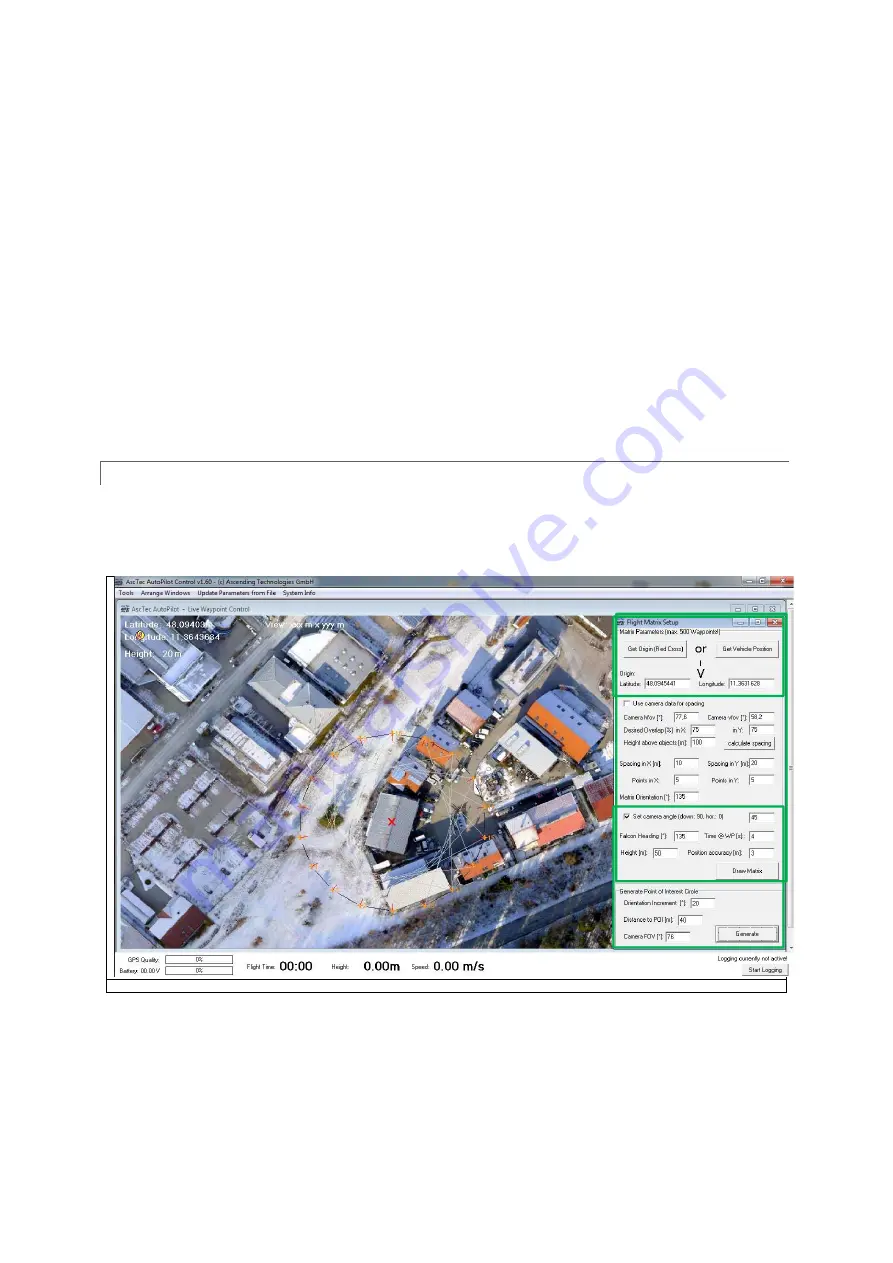
Open the MATRIX EDITOR by clicking the corresponding button in the COMMANDS
SECTION.
3.
Select GET ORIGIN (Red Cross) to start the matrix at the red cross or click GET VEHICLE
POSITION to start the matrix at the current position of the UAV.
4.
Then you need to enter a spacing between the individual waypoints for the X and Y directions
(X pointing to the right, Y pointing to the front) and the number of points in X and Y. “Matrix
Orientation” can be entered from 0° to 359°. It will rotate the whole matrix. At zero degrees X
is pointing towards East and Y is pointing towards North. The DESIRED FALCON HEADING
should always equal the Matrix orientation to make stitching images together easier. It can be
changed, if necessary.
5.
For TIME @ WP, HEIGHT, POSITION ACCURACY and SET CAMERA ANGLE please see the
chart at the top of that page under WAYPOINT PROPERTIES.
You can always click on DRAW MATRIX to see the result of your current entries, then change
numbers and control again, until the flight plan is what you want.
The settings in the MATRIX EDITOR can be saved and loaded for later flights.
POINT OF INTEREST CIRCLE
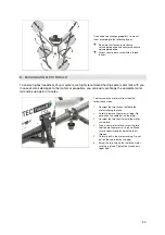
In the Matrix Editor, there is also the possibility to generate a Point of Interest Circle. This feature lets
you take photos of objects from a certain height from all directions. Especially useful when
generating 3D models of buildings.
© Ascending Technologies
To perform a Point of Interest Circle (POI) follow these steps:
1.
Define the center of the POI similar to the starting point of a matrix.
2.
Set the camera angle.
3.
Set TIME @ WP HEIGHT and POSITION ACCURACY.
4.
Define ORIENTATION INCREMENT, which is the rotation angle between photo positions.
5.
Define DISTANCE TO POI as the distance between photo position and center of the POI.

