

Product Manual
SECTION 4
VIRTUOSO 5460F
115057 REV L
19
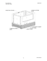
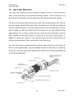
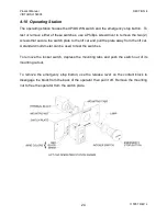
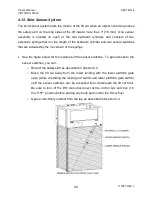
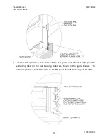
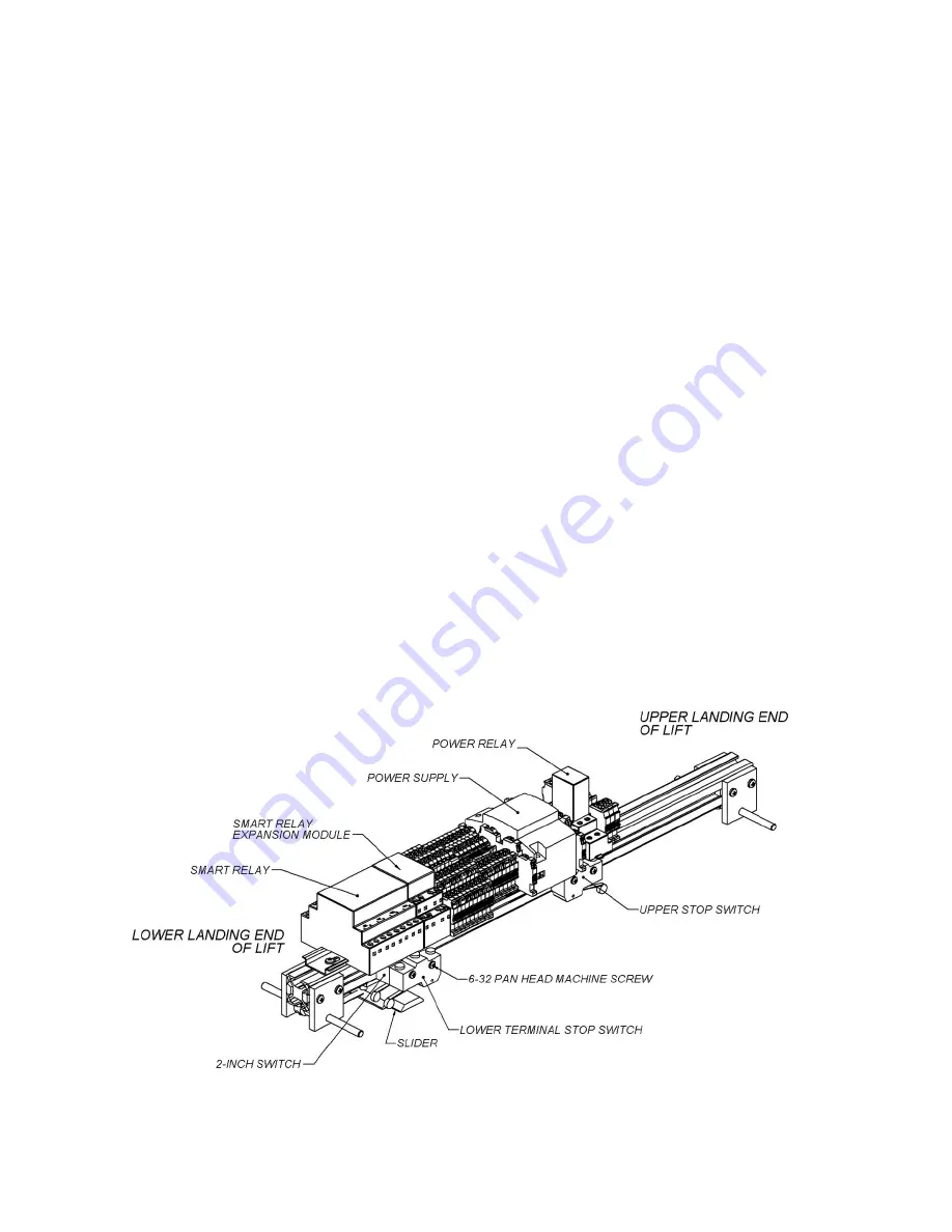
4.6 Upper Stop Mechanism
The upper stop mechanism can be accessed through the inner or outer left access
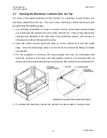
panel, or through the top of the left-hand machinery cabinet. Refer to Section 4.3 in
this manual for instructions on removing the top of the left-hand machinery cabinet.
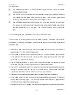
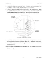
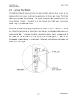
The lower terminal stop switch and two-inch switch are mounted side-by-side, with the
same two screws. Both switches have wires connected to their normally open (NO) and
common (COM) terminals. The lower terminal switch must be positioned so that the
slider activates its roller just before the lift car arrives at the lower landing (within
approximately 1/2” [13 mm]), and the two-inch switch must be positioned so that the
slider activates its roller when the lift car is within 2" [50 mm] of the lower landing. In
addition to shifting the position of the switches along the rail to achieve this, both
switches have adjustment screws at the base of their roller levers.
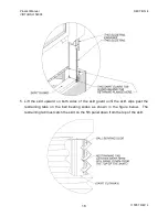
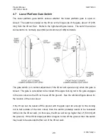
The upper stop switch must be positioned so that the slider activates its roller when the
lift car is at the upper landing. See the
Installation Guide
for instructions on positioning
it correctly. The upper stop switch has wires connected to its normally closed (NC) and
common (COM) terminals.
Summary of Contents for VIRTUOSO 5460F
Page 2: ......
Page 3: ...ASCENSION VIRTUOSO WHEELCHAIR LIFT 5460F MODEL SERIES PRODUCT MANUAL...
Page 11: ...Product Manual SECTION 1 VIRTUOSO 5460F 115057 REV L 5...
Page 34: ...Product Manual SECTION 4 VIRTUOSO 5460F 115057 REV L 28...
Page 45: ...Product Manual SECTION 5 VIRTUOSO 5460F 115057 REV L 39...
Page 53: ...Product Manual Notes VIRTUOSO 5460F 115057 REV L 47 Notes...
Page 54: ...Product Manual Notes VIRTUOSO 5460F 115057 REV L 48 Notes...
Page 55: ......


