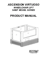
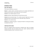
background image

Product Manual 


Introduction 

VIRTUOSO 5460F 


115057 REV L 

2

Getting Help 

If  you  have  a  question  or  problem  with  the  lift,  please  try  to  find  the  solution  in  this 

manual.  In particular, be sure to review the troubleshooting guide in Section 4.  If you 

are  not  able  to  resolve  the  problem,  please  contact  Ascension  as  indicated  below, 

making sure that you have the serial number of your lift ready.  The serial number can 

be  found  on  the  data  plate  located  inside  the  lift  car  on  the  upper  left  rail.    Also,  it  is 

recommended that you contact Ascension while in the immediate vicinity of your lift, as 

this will reduce the time required to properly diagnose the problem. 


Contacting Ascension 

Ascension's  business  hours  are  8  a.m.  to  5  p.m.  Mountain  Standard  Time,  Monday 

through Friday. 


 Telephone:  800-459-0400 

Mailing Address:  Ascension 


Fax:  520-881-4983 

  Customer Service 


Email:  sales@ascension-lift.com 

  PO Box 40020 

  Website:  ascension-lift.com 

  Tucson, AZ 85717-0020 

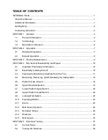
Summary of Contents for VIRTUOSO 5460F

Page 1: ...PRODUCT MANUAL ASCENSION VIRTUOSO WHEELCHAIR LIFT 5460F MODEL SERIES Patented see www ascension lift com patents...

Page 2: ......

Page 3: ...ASCENSION VIRTUOSO WHEELCHAIR LIFT 5460F MODEL SERIES PRODUCT MANUAL...

Page 4: ...Copyright 2020 Ascension a division of AGM Tucson Arizona This document or parts thereof may not be reproduced in any form by any method for any purpose without the written permission of Ascension...

Page 5: ...0 4 1 Important Preliminary Information 10 4 2 Electrically Isolating the Lift 10 4 3 Opening the Machinery Cabinets from the Top 11 4 4 Retracting Removing and Reinstalling the Safety Skirt 12 4 5 Pl...

Page 6: ...5 3 Testing the Relay Module 42 5 4 Testing the Power Supply 43 5 5 Testing the Power Relay 44 SECTION 6 Troubleshooting 45...

Page 7: ...formed on the lift Section 4 covers mechanical repair This includes component replacement as well as detailed procedures to disassemble test and reassemble major components Section 5 covers electrical...

Page 8: ...your lift ready The serial number can be found on the data plate located inside the lift car on the upper left rail Also it is recommended that you contact Ascension while in the immediate vicinity o...

Page 9: ...son MAXIMUM PASSENGER LOAD 750 pounds AVERAGE SPEED 7 feet per minute WORKING PRESSURE 900 psi maximum Physical INTERIOR DIMENSIONS 36 wide x 43 high x 54 long MATERIALS Platform base frame lifting de...

Page 10: ...t industry Lower Platform Gate The gate that serves the lower landing ground level Machinery Cabinet The enclosures in which the lifting mechanism is located There is one cabinet on each side of the l...

Page 11: ...Product Manual SECTION 1 VIRTUOSO 5460F 115057 REV L 5...

Page 12: ...the platform is at the upper landing Both gates are self closing The motion of the platform is controlled by any of the three operating switches located either in the lift car or remotely mounted Thes...

Page 13: ...immediately stop the platform Both gates must be closed for the lift to operate The lower platform gate can be opened only when the platform is at the lower landing The gate interlock is automatic Th...

Page 14: ...e it from its bracket 2 Swivel the pump linkage outward and then insert the hand pump handle into it Figure 1 3 To move the lift car upward pump the handle 4 To move the lift car downward pump the han...

Page 15: ...halts the downward movement of the platform 6 Verify that all of the screws securing the safety skirt to the platform frame are present and tight 7 Inspect the safety skirt for any visible damage 8 Ve...

Page 16: ...technician should be well versed in standard industrial safety practices and procedures In the United States of America electrical safety procedures are established in OSHA s Lockout Tagout Hazardous...

Page 17: ...t car These screws thread into coupling nuts attached to the other side of the machinery cabinet and function to compress the cabinet lid between the sides 2 Open the interior access panel and push up...

Page 18: ...on of the skirt may need to be retracted however sometimes it may be necessary to remove the whole skirt To remove the gate skirt perform all of the following steps If the skirt only needs to be retra...

Page 19: ...le skirt is to be removed raise or lower the lift car so that the lift car floor is approximately 15 380 mm off the ground 2 From inside the lift car remove the lower portion of the upper platform gat...

Page 20: ...At the front of the skirt use pliers or a similar tool to turn the skirt guide tubes counterclockwise until they release from the studs in the base You will need to lift the corners of the skirt to ga...

Page 21: ...stall the skirt guard onto the lift car by performing the following steps Refer to the figure at the top of the following page as necessary a Position the skirt guard underneath the ball bearing slide...

Page 22: ...16 5 Lift the skirt upward on both sides of the skirt guard until the skirt slips past the restraining tabs on the ball bearing slides as shown in the figure below The restraining tab must catch the s...

Page 23: ...t car one 1 at each corner Be sure to install the skirt support brackets between the skirt and the lift car frame See the figure below 8 Use a Phillips screwdriver to reinstall the remainder of the 32...

Page 24: ...REV L 18 4 5 Platform Gate Closers To make a platform gate close faster turn the gate closer counterclockwise 1 2 rotation at a time To make a platform gate close slower turn the gate closer clockwis...

Page 25: ...switch must be positioned so that the slider activates its roller just before the lift car arrives at the lower landing within approximately 1 2 13 mm and the two inch switch must be positioned so tha...

Page 26: ...operate only when the gate is closed The gate is considered to be closed if the upper locking rod in the gate engages in the lock cutout as the lift car moves off the ground See the left hand figure...

Page 27: ...ift car If necessary see Section 4 4 for instructions on retracting the skirt The switch is held in place by two 2 14 mm nuts To adjust the switch i e to extend it or recess it use a 14 mm wrench or s...

Page 28: ...e lift car will operate only when the gate is closed The gate is considered to be closed if the gate handle does not protrude beyond the back edge of the lift car The switch itself cannot be adjusted...

Page 29: ...e skirt The switch is of the normally open NO type and can be tested using a standard multi meter To access the switch for testing or replacement retract the upper left corner of the lift car skirt wh...

Page 30: ...t secure the switch plate to the lift car and pull the plate away from the lift car A standard multi meter can be used to test the switches To remove the rocker switch depress the mounting tabs and pu...

Page 31: ...the emergency stop button Release the emergency stop button to turn off the alarm If the alarm does not sound when the emergency stop button is pressed the alarm battery must be replaced The battery...

Page 32: ...the movement of the springs See the figure below for the locations of the sensor switches To gain access to the sensor switches you can o Retract the safety skirt as described in Section 4 4 o Move th...

Page 33: ...head cap screws that secure the switch to the bracket and hose clamp as this could crack the switch case o The pre travel on the switch should be minimized such that the switch audibly clicks its cont...

Page 34: ...Product Manual SECTION 4 VIRTUOSO 5460F 115057 REV L 28...

Page 35: ...ting or removing any of the four components located in the manifold It is recommended that you place paper towels below the component to be removed to catch the several ounces of hydraulic fluid that...

Page 36: ...manifold the counterbalance valve is malfunctioning and must be replaced with the lift car at the lower landing Before removing this valve pull the electrical harness connectors off of the coil termin...

Page 37: ...of the screws attaching the four glazing strips to the lift s exterior The window and strips can then be removed as a single unit To reinstall a window position the window assembly in its original ins...

Page 38: ...n head screws and the bridge plate secured to the skirt guard with four 4 flat head screws 3 Detach the protective skirt from the long sides of the lift car by removing the ten 10 pan head screws on e...

Page 39: ...rizontal slots in the ball bearing slide rails 2 Use a 5 16 wrench to secure the skirt to the skirt guard with the 3 hex head screws removed in Step 6 above 3 Position the skirt guard underneath the b...

Page 40: ...34 7 Lift the skirt upward on both sides of the skirt guard until the skirt slips past the restraining tabs on the ball bearing slides as shown in the figure below The restraining tab must catch the s...

Page 41: ...car frame See the figure below 10 Use a Phillips screwdriver to reinstall the remainder of the ten 10 pan head screws that secure the sides of the skirt to the lift car 11 Use a Phillips screwdriver t...

Page 42: ...sure to catch the screws as they are removed To install a ball bearing slide into the lift car frame reverse the above instructions Be sure to install the two 2 8 18 x 3 8 self tapping pan head screw...

Page 43: ...ny part of the electrical system industrial electrical safety practices should be rigorously adhered to including Danger Tags While repairs are underway a danger tag must be attached to the disconnect...

Page 44: ...t Manual SECTION 5 VIRTUOSO 5460F 115057 REV L 38 Virtuoso Wiring Schematic Safety Under Pan option not shown For models with Safety Under Pan there are 16 NC switches in series with the Left Skirt sw...

Page 45: ...Product Manual SECTION 5 VIRTUOSO 5460F 115057 REV L 39...

Page 46: ...back of the switch See the table below for information on the type of each switch and in which section of this manual to find information on accessing the switch Switch Type Section Upper Stop Switch...

Page 47: ...ift car is more than 2 off the ground Upper locking rod is disengaged lift car is less than 2 off the ground or lower platform gate is open Platform Gate Switches I4 L Both upper and lower platform ga...

Page 48: ...orming any testing on it To test the function of the relay module refer to the logic diagram on page 38 If the relay module is not receiving power check for and correct the following conditions as nec...

Page 49: ...minated the unit is supplying 12VDC If the LED is not illuminated check to see that the AC supply is on If AC power is being supplied use a multi meter to check for the voltage drop between a and a te...

Page 50: ...e to the 13 contact on the power relay If this causes the lift car to rise then the power relay is functional If it does not then measure the voltage drop across the same power relay contacts indicate...

Page 51: ...he upper platform gate switch actuator 4 8 Component failure Electrical testing possible component replacement 5 2 Upper landing gate switch is out of adjustment Adjust the upper landing gate switch N...

Page 52: ...ance valve malfunction Replace counterbalance valve 4 13 Lift car does not stop automatically at the upper landing Upper stop mechanism is not set correctly Adjust upper stop mechanism 4 6 Upper stop...

Page 53: ...Product Manual Notes VIRTUOSO 5460F 115057 REV L 47 Notes...

Page 54: ...Product Manual Notes VIRTUOSO 5460F 115057 REV L 48 Notes...

Page 55: ......

Page 56: ...Printed in the U S A 115057 REV L...

Reviews: