Maintenance & Repair Manual
SECTION 3
VIRTUOSO 5460P
21
110057 REV K
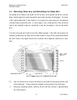
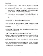
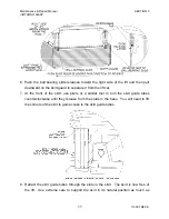
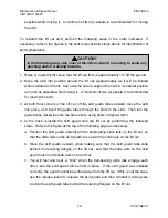
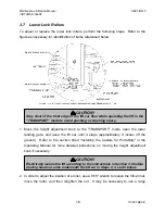
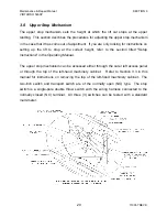
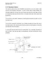
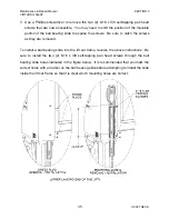
The upper stop mechanism has four (4) adjustable components: the transport switch,
the stop switch, the two-inch switch, and the ball plunger. See the figure on the
previous page for identification of these components. These four (4) components must
be adjusted so that the following four (4) conditions are met:
1.
The stop switch roller is actuated by the actuator ramp at the same time that the ball
plunger "clicks" into the plunger slot.
For fine adjustments to the stop switch, use a
1/16" hex key to adjust the set screw at the lever base. For gross adjustments to the
stop switch, use a 5/64" hex key to turn the two (2) 6-32 x 1-1/4 mounting screws.
Or, to adjust the ball plunger mounting bracket, use a 1/8" hex key to turn the two (2)
10-32 x 3/4 screws. After adjusting the ball plunger mounting bracket, the two-inch
switch may need to be readjusted as well (see item 2 below).
2.
The two-inch switch is actuated whenever the lift car is less than two inches off the
ground.
To adjust the two-inch switch, use pliers and/or a 5/8" wrench to move the
nuts on the barrel of the switch. To check the adjustment of the 2" switch, return the
lift car to the ground. Then:
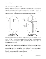
a. With the lower landing gate open, depress the lower landing gate switch (refer
to Section 3.9), and raise the lift car by holding an operating switch "Up". If
the lift car does not stop before it has moved 2" off the ground, the body of the
switch needs to be adjusted further from the mounting bracket.
b. With the lower landing gate closed, hold an operating switch "Up" to raise the
lift car off the ground. If the lift car stops or "jumps" within 4" of the ground,
the body of the switch needs to be adjusted closer to the mounting bracket.
3.
The transport switch is actuated whenever the height adjustment knob is in the
"TRANSPORT" position.
To adjust the transport switch, use pliers and/or a 5/8"
wrench to move the two (2) nuts on the barrel of the switch.
4. The ball plunger has a positive engagement with the plunger slot.
To adjust the
strength of the "click" that is felt when the ball plunger engages the plunger slot, use
a 3/4" wrench to loosen the 1/2-13 nut and then turn the ball plunger with a standard
screwdriver. Turn the ball plunger clockwise to make the "click" stronger or
counterclockwise to make the "click" weaker.


