Maintenance & Repair Manual
SECTION 4
VIRTUOSO 5460P
39
110057 REV K
4.2 Testing the Switches
Each of the lift's switches can be tested by locating the switch, removing the switch from
the lift if necessary, and checking for continuity across the contacts on the back of the
switch. See the table below for information on the type of each switch and in which
section of this manual to find information on accessing the switch.
Switch Type Section
Transport Switch
SPST, NO
3.8
Two-Inch Switch
SPST, NO
3.8
Upper Stop Switch
SPDT, NC circuit used
3.8
Lower Landing Gate Switch SPDT, NO circuit used
3.9
Upper Landing Gate Switch SPST, NO
3.10
Locking Rod Switch
SPST, NO
3.11
Emergency Stop Switch
Push-to-break 3.12
Rocker Switch
(Mom. On)-Off-(Mom. On)
3.12
Override Keyswitch
Off-(Mom. On)
3.13
ON/OFF Switch
On-Off
4.1
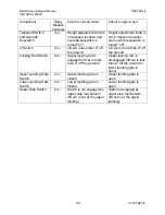
Alternately, most of the lift's switches can be tested at the relay module, which operates
on 12 VDC power. Before performing any checks at the relay module, verify that the
module itself is receiving power (refer to Section 4.3). If the module is receiving power,
then the function of the lift's switches can be verified by testing for continuity across the
relay module's contacts as shown in the table below.
Component Relay
Module
Contacts
Circuit is closed when:
Circuit is open when:
Rocker Switch
I8-L+
Rocker is pushed up
Rocker is at rest or
pushed down
I7-L+
Rocker is pushed down
Rocker is at rest or
pushed up


