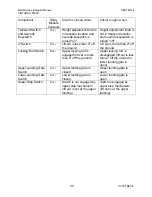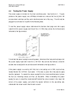
Maintenance & Repair Manual
SECTION 5
VIRTUOSO 5460P
47
110057
REV
K
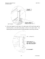
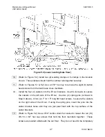
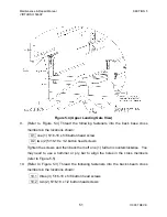
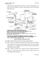
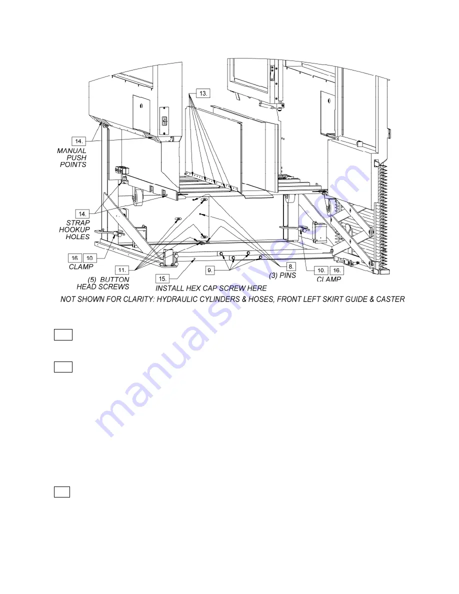
Figure 5.2 (Lower Landing Gate View)
10. (Refer to Figure 5.2) Install two (2) welding clamps or C-clamps in the location
shown. These clamps should hold the vertical rails together securely.
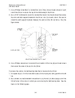
11. (Refer to Figures 5.1 & 5.2) Use a 3/16" hex key to remove the eight (8) button
head screws from the back base cross members.
12.
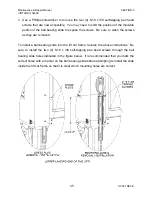
Install the four (4) casters into the lift car brackets. Use the lock pins to secure
the casters on the left side of the lift car. Use two (2) spring pins (removed in
Step 8 above), or two (2) 1" to 1.5" long flat head screws, to secure the casters
on the right side of the lift car. If using the spring pins, insert the pins into the
caster bracket holes until they are just past flush with the top surface of the
caster brackets.
13.
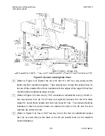
(Refer to Figure 5.2) Use a 9/16" combo wrench or socket to loosen the ten (10)
3/8-16 x 3/4" hex cap screws that hold the floor members together. These
screws are located underneath the car floor. They do not need to be completely

