Maintenance & Repair Manual
SECTION 5
VIRTUOSO 5460P
48
110057
REV
K
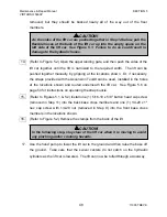
removed, but they should be backed nearly all of the way out of the floor
members.
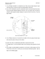
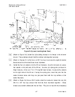
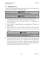
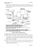
14. (Refer to Figure 5.2) Open the upper landing gate, and then push the sides of the
lift car together until the lift is narrowed to the required width. The lift can be
pushed together manually, by gripping at the locations shown. Or, if necessary,
the straps provided with the Ascension Toolkit can be used, installed in the holes
at the locations shown and routed underneath the lift car. See Figure 5.6 on
page 54 for instructions on operating the strap buckle.
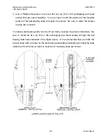
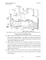
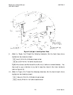
15. (Refer to Figures 5.1 & 5.2) Install one (1) 5/16-18 x 5/8" button head cap screw
(removed in Step 11) into the back base cross members and one (1) 1/4-20 x 1"
hex cap screw with 1/4-20 nut (removed in Step 9) into the front base cross
members in the locations shown.
16. (Refer to Figure 5.2) Remove the clamps from the back of the lift.
17. Use the hand pump to lower the lift car to the ground and then raise the base off
the ground. Take care that the swivel casters do not catch on the hydraulic
cylinders as the lift car is lowered. The lift can now be rolled through a doorway.
CAUTION!
In the following step, stay clear of the lift car when it is moving to avoid
any pinching and/or crushing hazards.
CAUTION!
As the sides of the lift car are pushed together in Step 14 below, pull the
flexible hoses at the back of the lift car up into the empty space on the
left side of the lift car. See Figure 5.1. Failure to do so could result in
damage to the hydraulic hoses.

