Maintenance & Repair Manual
SECTION 5
VIRTUOSO 5460P
52
110057
REV
K
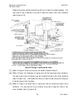
Tighten the screws and then back them off one (1) full turn counterclockwise. You
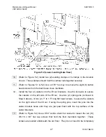
may need to use a hammer or pry bar to align the holes in the cross members
(refer to figure 5.5).
Figure 5.5 (Upper Landing Gate View)
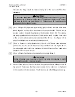
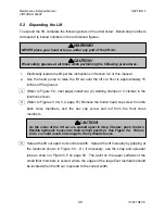
11. (Refer to Figure 5.3) Remove the two (2) clamps installed in Step 3.
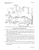
12. (Refer to Figure 5.4) Install two (2) spring pins into the back base cross members.
You may need to use a hammer or pry bar to align the holes in the cross members
(refer to Figure 5.5). Then tighten the three (3) button head screws (from Step 9)
in the back base cross members.
13. (Refer to Figure 5.3) Install one (1) spring pin into the horizontal I-beam cross
members. You may need to use a hammer or pry bar to align the holes in the
cross members (refer to Figure 5.5).


