Maintenance & Repair Manual
SECTION 5
VIRTUOSO 5460P
53
110057
REV
K
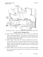
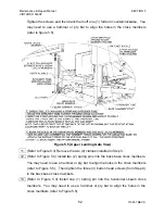
14. (Refer to Figure 5.4) Use a 3/16" hex key to turn the four (4) adjustment screws
(two (2) on each side) at the back of the lift car exactly three (3) full rotations
clockwise.
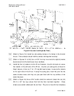
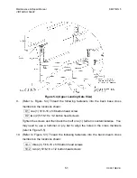
15. (Refer to Figure 5.3) Remove the two (2) spring pins from the lift car caster
brackets (on the right side of the lift car) and install them into the vertical I-Beam
cross members. You may need to use a hammer or pry bar to align the holes in
the cross members.
16. Tighten the five (5) button head screws (from Step 10) in the I-beam cross
members.
17. (Refer to Figure 5.4) Reattach the dock plate to the lift car by installing the
following fasteners:
17.1 Two (2) Phillips #10 x 1/2 flat head screws that secure the dock plate
hinge bracket to the lift car floor in the back, center of the floor.
17.2 Four (4) 1/4-20 x 1/2 button head screws with lock washers that secure
the dock plate hinge bracket to the lift car sides, two (2) on each side.
(Use a 5/32" hex key.)
18. (Refer to Figure 5.4) Reconnect the gate closer spring to the upper landing gate
and then reinstall the e-clip to keep it and the hydraulic damper in place.
19. (Refer to Figure 5.4) Reconnect the dock plate tether to the upper landing gate
using the footman's loop and two (2) #10 x 3/4 flat head screws.
20. Tighten the hex cap screws installed in Step 7 above.
21. Reinstall the lift car safety skirt. Refer to Section 3.4 of this manual.
22. Return the lift car floor to its normal position and pump the lift onto its wheels.
23. Move the lift to the desired location and set it up according to the instructions in the
Operating Manual
and then verify the correct operation of the lift as described in
Section 5.3.
WARNING!
Verify the correct operation of the lift, as described in Section 5.3, before
using the lift. Failure to do so could result in serious injury to the user.


