10 Chapter 2 Installation and Wiring
Series 230 Automatic Transfer Switch C2000 Intelligent Controller User Manual
2.2 Controller Interface and Connection Cable Information
2.2.1 Controller Interface
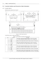
C2000 Connector Labels as shown in Fig 2-6
X4
User Connector
X1
Power Connector
X2
Signal Connector
X3
User Connector
Figure 2-6 C2000 Controller Interfaces
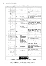
Pin definition as table 2-3, table 2-4 and table 2-5
Table 2-3 Power connection Pins definition of C2000 controller
Port
Port Label
Pin Definition
X1
1
U1A(L)
A Phase Power and signal detect (voltage & frequency) of Source I for three phase
Or L line Power and signal detect (voltage & frequency) of Source I for single phase
2
Blank
3
U1B
B Phase Power and signal detect (voltage & frequency) of Source I for three phase
4
Blank
5
U1C(N)
C Phase Power and signal detect (voltage & frequency) of Source I for three phase
Or Neutral Power and signal detect (voltage & frequency) of Source I for single phase
6
Blank
7
Blank
8
U2A(L)
A Phase Power and signal detect (voltage & frequency) of Source II for three phase
Or L line Power and signal detect (voltage & frequency) of Source II for single phase
9
Blank
10
U2B
B Phase Power and signal detect (voltage & frequency) of Source II for three phase
11
Blank
12
U2C(N)
C Phase Power and signal detect (voltage & frequency) of Source II for three phase
Or Neutral Power and signal detect (voltage & frequency) of Source II for single phase

