Chapter 2 Installation and Wiring 13
ASCO Series 230 Automatic Transfer Switch C2000 Intelligent Controller User Manual
2.2.2 Connection Cable Information
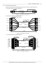
If the user needs to modify a connection cable, user can make it according to the cable drawings below:
1. Controller ground cable drawing LTSC2000SLW03.
200±10
LTSC2000SLW03
(OT2-4)*2
UL1015 14AWG Yellow/Green
Grounding Cable
Figure 2-7 Cable Diagram of Grounding Cable
2. Controller Power Cable Drawing 230S400SLW01-1
1500±30
(TP508P-00-12P/MSTB2.5/12-5.08)*2
Controller
Transfer Switch
230S400SLW01-1
UL2464 20AWG*6C Grey
300V
1 Black
3 Brown
5 Red
8 Orange
10 Yellow
12 Green
12 Green
10 Yellow
8 Orange
5 Red
3 Brown
1 Black
Power Cable
Figure 2-8 Cable Diagram of Power Cable
3
.
Controller signal cable drawing 230S400SLW01-2
1500±30
TP381P-00-14P
/MC1.5/14-ST-3.81
Controller
Transfer Switch
TP381P-00F-14P
/MC1.5/14-SFT-3.81
UL2464 22AWG*12C Gray
300V
1 Black
2 Brown
3 Red
4 Orange
5 Yellow
6 Green
7 Blue
8 Purple
9 Gray
10 White
11 Pink
12 Light Blue
13
14
14 Black
13 Brown
12 Red
11 Orange
10 Yellow
9 Green
8 Blue
7 Purple
6 Gray
5 White
4 Pink
3 Light Blue
2
1
230S400SLW01-2
Signal Cable
Figure 2-9 Cable Diagram of Signal Cable

