background image

Installation, Operation and Maintenance Manual

8221  RevD  08-18

6

INSTALLATION  

Pre-Plan your installation. You need to accomplish the following:

• 

Meet all National and Local codes (NEC

®

 Article 285, and CEC address SPDs).

• 

Confirm System voltage to SPD voltage (a 120V SPD will fail instantly on 240V, 277V, etc.).

• 

Mount SPD as close to panel or equipment as possible to keep leads short. (Long leads hurt 

performance substantially.) 

• 

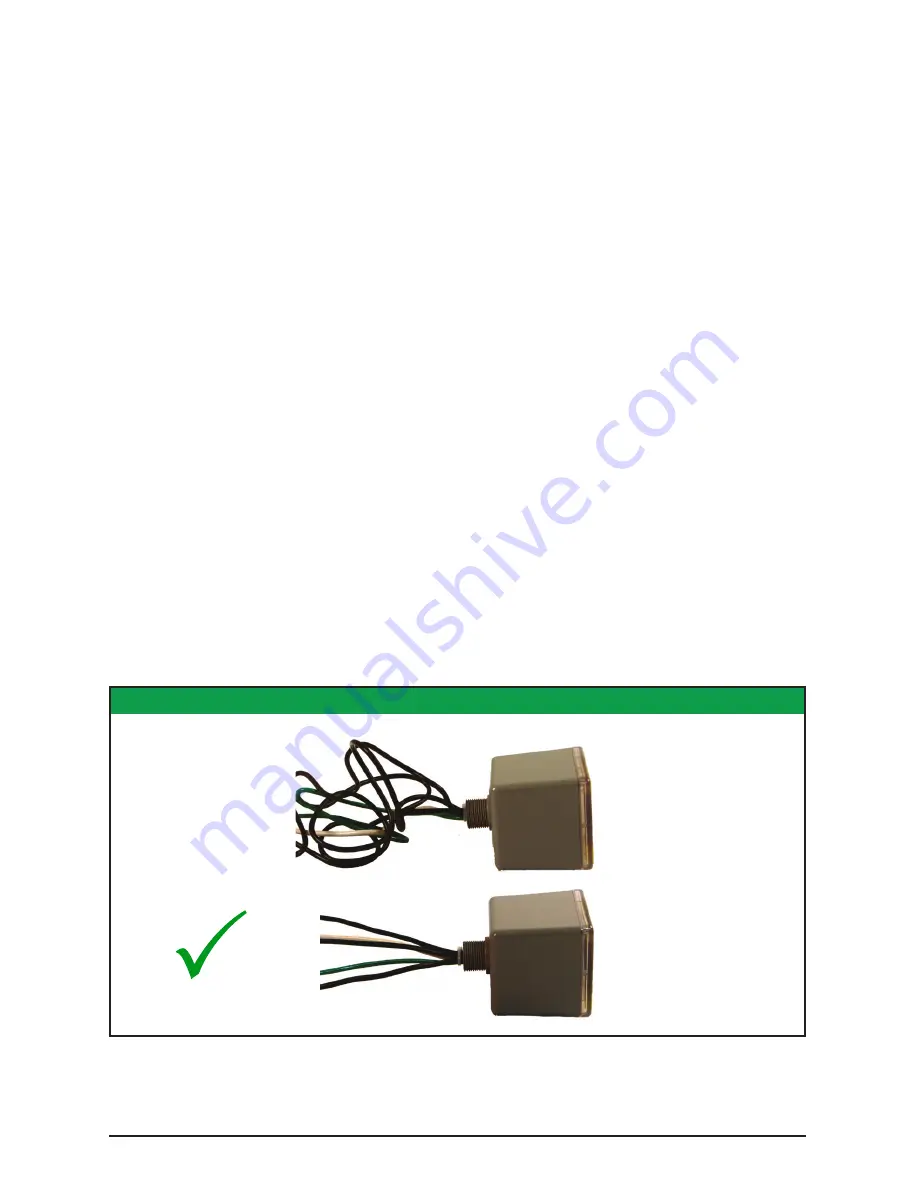
Ensure leads are as short and straight as possible, including neutral and ground. If using a 

breaker, use a breaker position that is close to the SPD and the panel’s neutral & ground.

• 

If using a breaker, recommended breaker size is 30A due to 10 AWG conductor.

• 

Make sure system is grounded per NEC

®

 and CEC and clear of faults before energizing SPD. (An 

inadvertent system problem may fail the SPD.) 

• 

Never Hi-Pot test Any SPD. (Hi-potting will cause SPD to prematurely fail.)

1.  Use voltmeter to check voltages and ensure correct SPD. See Data Sheet for specs and wire-

outs.

2.  Determine Mounting method (See Figure 6) – weather resistant equipment may be required.

3.  If SPD has optional Dry Contact, pre-plan its installation.

4.  Remove power from panel/source. Confirm panel/source is de-energized.

5.  Identify breaker location and SPD location. Position SPD such that LED is best visible.

6.  Mount SPD – weather resistant applications require additional sealing, O-rings, etc.  

(not included)

•  Remove an appropriately sized knockout from panel. 

•  Connect conductors as appropriate – leads should be short and straight as possible  

(Connect a system Hi-Leg to SPD’ Phase B).

7.  Label or mark conductors as appropriate (neutral: white, ground: green, energized: black, hi-

leg: orange).

8.  Make sure system is bonded per NEC

®

 and CEC and is clear of hazards or faults before 

energizing. (N-G bonding not per NEC

®

 and CEC will fail SPDs: This is the #1 cause of SPD 

failures)

9.  Energize and confirm proper operation of green LED indicator and/or options.  

(Affix supplemental label accessory if appropriate. See Figure 6.)

FIGURE 2: LEADS SHORT & STRAIGHT

X


NOT 

GOOD

GOOD

Cut off 

Excess Length 

Do Not Loop or Coil

Short & Straight

Summary of Contents for 400 Series

Page 1: ...Surge Protective Devices Installation Operation Manual S50A ...

Page 2: ...icos incluyendo DINP que es conocido por el Estado de California como causantes de cáncer y DIDP que es conocido por el Estado de California como causante de defectos de nacimiento u otros daños reproductivos Para mayor información visite www P65Warnings ca gov AVERTISSEMENT Ce produit peut vous exposer à des agents chimiques y compris DINP identifiés par l État de Californie comme pouvant causer ...

Page 3: ...Figure 4 Nipple Figure 5 Dimensions Weight Figure 6 S50A Mounting Options Voltage Rating Application SPDs on Ungrounded Systems Connecting Optional Form C Dry Contact Audible Alarm Figure 7 Leads 6 6 7 7 8 8 8 9 9 9 NORMAL OPERATION Green LED Indicator Form C Dry Contact and Audible Alarm Option Maintenance Troubleshooting Service 10 10 10 10 10 INTRODUCTION Figure 1 NEC Article 285 UL 1449 4 Part...

Page 4: ...R MUST SEAL THE CONDUIT NIPPLE USING WATERTIGHT FITTINGS NOT INCLUDED TO ENSURE A WATERTIGHT CONNECTION READ THIS MANUAL IN ITS ENTIRETY PRIOR TO INSTALLING In the late 2000 s there were significant nomenclature changes associated with a revision to UL 1449 and 2008 NEC Article 285 The S50A complies with latest regulatory actions and is UL 1449 CSA 22 2 No 269 listed as such VZCA E321351 There is ...

Page 5: ...luding leads See UL Label markings on SPD or see Data Sheet for specs Supplemental overcurrent protection is not required to protect this SPD However NEC and CEC convention requires that connecting conductors have overcurrent protection in Type 2 applications Follow applicable codes This device features internal overcurrent and overtemperature protection that will disconnect effected surge suppres...

Page 6: ... See Data Sheet for specs and wire outs 2 Determine Mounting method See Figure 6 weather resistant equipment may be required 3 If SPD has optional Dry Contact pre plan its installation 4 Remove power from panel source Confirm panel source is de energized 5 Identify breaker location and SPD location Position SPD such that LED is best visible 6 Mount SPD weather resistant applications require additi...

Page 7: ...mply with the National Electrical Code NEC and applicable local codes V WARNING A B C G N BREAKER Type 1 or individual equipment installations may vary Use closest breaker to SPD Locate SPD close to intended breaker Keep Leads Short as Possible Avoid Sharp Bends Rotate S50A such that LED indicator is most visible Outdoor installation requires appropriate weather sealing at nipple gasket sealing co...

Page 8: ...ault conditions During these fault conditions any electrical equipment including an SPD may be subjected to voltages which exceed their designed ratings This information is being provided to the user so that an informed decision can be made before installing any electrical equipment on an ungrounded power system FIGURE 5 DIMENSIONS WEIGHT 3 26 3 26 1 15 4 13 3 4 14 Sized for std 35mm DIN Rail 3 31...

Page 9: ...r failed wiring whereas Normally Open does not If the dry contacts are not utilized insulate lead ends coil and secure Audible Alarm will still function correctly The contact is rated 250V 5A Higher energy applications require supplemental relaying This option monitors suppression element condition and is not intended for use as phase loss or phase detection monitoring NORMAL OPERATION Green LED I...

Page 10: ...s also known as Temporary Overvoltages TOVs In this context Sustained Overvoltages may be only a few cycles Failed SPDs tend to be symptoms not root causes We suggest treating a failed SPD as a canary in the coal mine as there may be larger issues at play As a generalization the single largest killer of SPDs is reference to ground issues If the SPD shows problems on startup there is reasonable cha...

Page 11: ...Installation Operation and Maintenance Manual 8221 RevD 08 18 11 ...

Page 12: ...iterature ASCO assumes no responsibility and disclaims all liability for damages resulting from use of this information or for any errors or omissions 2018 ASCO Power Technologies All Rights Reserved 14550 58th Street North Clearwater Florida 33760 P 800 727 0669 F 727 539 8955 W www surgeassure com ...

Reviews: