background image

EN 24

Summary of Contents for CI41238G

Page 1: ...Instructions for use Cooker hood CI41238G ES12ENTFE ...

Page 2: ...EN Manual EN 3 EN 23 Pictograms used Important information Tip ...

Page 3: ... Your cooker hood Introduction 4 Use Description 5 Operation 6 Cleaning filters 8 Maintenance Cleaning 9 Installation General 12 Connection 13 Build in dimensions 14 Technical specifications 22 Appendix Disposal 23 ...

Page 4: ...r with the features of this appliance Please read the appliance s safety and maintenance instructions Please retain the operating and installation instructions as these may be useful for future reference Please read the separate safety instructions prior to use YOUR COOKER HOOD ...

Page 5: ...tus 6 Timer function indicator 7 Clean Air function indicator 8 Switching on and increasing air extraction capacity 9 Switching on timer function Note Prior to activating or deactivating a function the motor and lighting should be switched off If you have a cooker hood with a carbon filter you should activate the carbon filter indicator as described in the Cleaning filters paragraph 1 2 3 4 5 6 7 ...

Page 6: ... To switch off the cooker hood from whatever setting press and hold the button 2 for at least 2 seconds Alter the number of speed settings models with 9 speed settings You can choose between 9 speed settings standard or 5 speed settings Press and hold the button 2 and button 8 for at least 5 seconds This selects the 5 speed setting option Press and hold the button 2 and button 8 again for at least...

Page 7: ...s lit its strength will be reduced automatically by 30 40 once the timer has finished Note If the intensive setting has been selected you cannot activate the timer function Clean Air function The Clean Air function allows you to freshen the air in your kitchen for a maximum of 12 hours Switch off the cooker hood Press and hold the timer button 9 for approximately 4 seconds The cooker hood will swi...

Page 8: ...uld then be cleaned or replaced Reset the memory by simultaneously pressing and holding the 2 and 8 buttons until the carbon filter indicator 3 stops flashing Switching on carbon filter indicator Simultaneously press and hold the 8 button and the lighting button 1 until the carbon filter indicator 3 flashes twice The carbon filter indicator is activated Switching off carbon filter indicator Simult...

Page 9: ...r and a soft cloth Then wash off with clean water Do not use aggressive cleaning agents such as caustic soda The cooker hood finish stays in good condition if it is buffed periodically following the application of wax Stainless steel cooker hoods Do not use scouring pads or other abrasive cleaners on stainless steel cooker hoods Finish with a non abrasive non polishing agent and buff the stainless...

Page 10: ... agent and a damp cloth Dry off with a paper towel Replacing cassette filter The filter should be placed with the locking mechanism on the side Open the filter access hatch The notches at the side of the filter will then slot in Hold the access hatch in this position when placing the filters 1 Slot the notches at the back of the filter in the specially designed opening to the side of the cooker ho...

Page 11: ... more than 3 years or if it has been damaged It is important that the grease filters and the regenerable active carbon filter are thoroughly dry before repositioning Replacing the carbon filter The grease filters should first be removed before replacing the carbon filter Press the two B buttons on the carbon filter inwards Tilt the carbon filter downwards to remove it Repeat the steps above in rev...

Page 12: ...east 65 cm With an electric ceramic or induction hob this distance should be at least 55 cm Follow the applicable local regulations regarding the ventilation of gas appliances The cooker hood will work better with a short outlet pipe and the fewest bends possible Prior to drilling check that there are no pipes or cables present The cooker hood connection pipe is 120 mm 125 mm or 150 mm in diameter...

Page 13: ...mains is carried out as follows BROWN phase L BLUE phase N YELLOW GREEN Earth During the electrical connection make sure that the electrical socket is equipped with earth connection This built in unit has been provided with a power plug When installing the hood make sure that this plug remains accessible Please note If you want to make a fixed connection make sure that an omnipolar switch with a c...

Page 14: ...allation height The minimum distance between a gas hob s pan supports and the lower edge of the hood should be 65 cm For use with an electric ceramic or induction hob this distance should be at least 55 cm Build in dimensions ...

Page 15: ...ontrol panel Fig 2 For assembly screws should be used that are suitable for the wall type for example reinforced concrete plasterboard etc If screws and plugs are supplied with the hood make sure in advance that these are suitable for the wall on which the hood is to be installed Drill four holes Ø 8 in the ceiling and affix the four plugs Form the air outlet opening A Fig 3 Connect the tube to th...

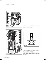
Page 16: ...EN 16 INSTALLATION To install the cooker hood fit the electric unit D upright Secure the bracket with the four screws G as indicated in Figure 6 Fig 5 Fig 6 ...

Page 17: ...N 17 INSTALLATION Secure the air outlet pipe H not supplied to the connection flange F as indicated in Figure 7 Take the bottom section of the frame C and fix this to the motor housing Fig 8 Fig 7 Fig 8 ...

Page 18: ...nstruction C to the motor housing using the 4 screws E Fig 9 Take the top section of the frame B and slot this in the bottom section C Adjust the height according to the sizes in Figure 10a and secure these with the 8 screws G supplied Fig 10a ...

Page 19: ...EN 19 INSTALLATION Connect the bottom shaft A with the top one B as indicated in Figure 11 Fig 11 ...

Page 20: ...the bracket B Figure 12 steps 2 3 Put the hood in position so that the safety pin clicks in the gap in the bracket B Figure 12 step 4 Please note Secure the hood directly onto the bracket B with the 6 screws D Fig 13 Take the safety bracket L and secure this to the ceiling plate with the two screws M as indicated in Figure 14 steps 1 2 Fig 12 Fig 13 Fig 14 ...

Page 21: ... not supplied to the air outlet opening A Fig 15 Insert the plug into the disconnected wall socket Fig 16 Connect the shaft B to the ceiling plate using the two screws F Fig 17 Fig 15 Fig 16 Fig 17 Test if the appliance operates correctly ...

Page 22: ...l 4 Air flow Noise Pressure Level 5 Air flow Noise Pressure Level 6 Air flow Noise Pressure Level 7 Air flow Noise Pressure Level 8 Air flow Noise Pressure Level 9 Air flow Noise Pressure Taal Language Engels English Keuringstype Approval type Australië AU 347 m h 47 dB A 314 Pa 406 m h 51 dB A 408 Pa 488 m h 56 dB A 418 Pa TECHNICAL SPECIFICATIONS 248 m h 40 dB A 170 Pa 220 240 V 50 60 Hz 833 m h 69 dB...

Page 23: ...egulations The product has been marked with a crossed out dustbin symbol to remind you of the obligation to dispose of electrical household appliances separately This means that the appliance may not be included with normal domestic refuse at the end of its service life The appliance must be taken to a special municipal centre for separated waste collection or to a dealer providing this service Se...

Page 24: ...EN 24 ...

Page 25: ...EN 25 ...

Page 26: ...545737 545737 545737 VER 2 13 01 2016 ...

Reviews: