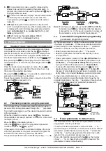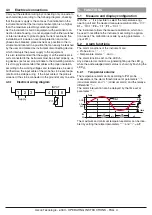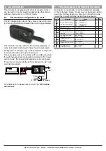
Ascon Tecnologic - e30V - OPERATING INSTRUCTIONS - PAG. 1
e30V
DIGITAL
ELECTRONIC
THERMOMETER
OPERATING INSTRUCTIONS
18/01 - code: ISTR_M_e30V_E_01_--
ASCON TECNOLOGIC S.rl.
Viale Indipendenza 56, 27029 - VIGEVANO (PV) ITALY
Tel.: +39 0381 69871 - Fax: +39 0381 698730
http:\\www.ascontecnologic.com
info@ascontecnologic.com
PREFACE
D
D
This manual contains the information necessary for
the product to be installed correctly and also instruc-
tions for its maintenance and use; we therefore recom-
mend that the utmost attention is paid to the following
instructions and to save it.
This document is the exclusive property of Ascon Tecnologic
S.rl. which forbids any reproduction and divulgation, even
partially, of the document, unless expressly authorized.
Ascon Tecnologic S.rl. reserves the right to make any formal
or functional changes at any moment and without any notice.
Ascon Tecnologic S.rl. and its legal representatives do not
assume any responsibility for any damage to people, things
or animals deriving from violation, wrong or improper use or
in any case not in compliance with the instrument features.
D
D
Whenever a failure or a malfunction of the device
may cause dangerous situations for persons, thing
or animals, please remember that the plant has to be
equipped with additional electromechanical devices
which will guarantee safety.
1. INSTRUMENT DESCRIPTION
1.1
General description
The
E30V
model is a digital microprocessor electronic ther-
mometer with
NTC
input probes equipped with functions for
temperature alarms
.
The instrument is available with a keyboard or without a
keyboard (in this case, any parameter programming can only
take place via device
A01
).
1.2
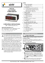
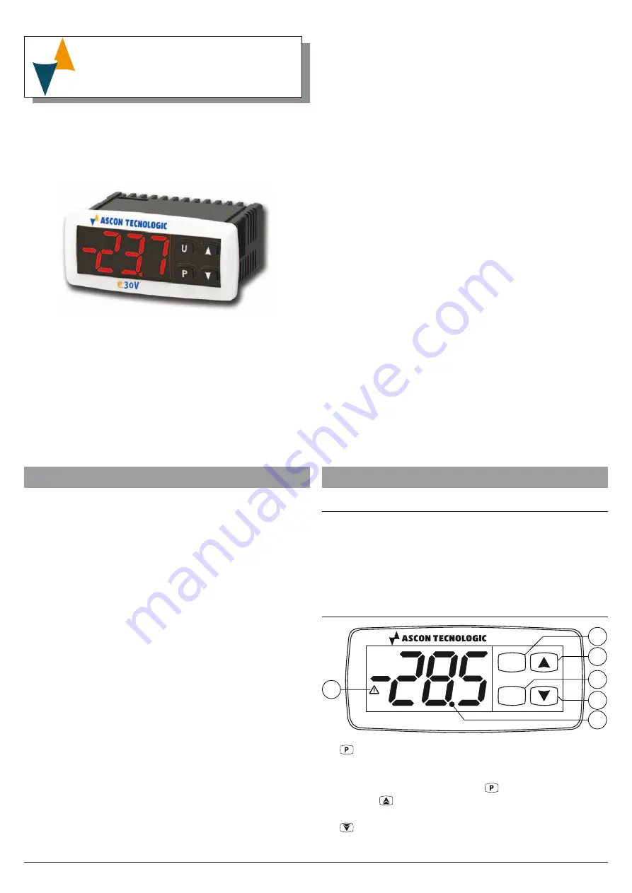
Front panel pescription
P
U
e30V
1
2
3
4
5
6
1.
:
Pressed for 5 s allows to access the parameters
programming the functions. In programming mode is
used to enter the parameter edit mode and confirm the
values. In programming mode
can be used together
with the
key to change the programming level of the
parameters.
2.
:
In programming mode is used for decreasing the
values to be set and for selecting the parameters..
Index
1. Instrument description ............................................... 1
2. Programming ............................................................... 2
(parameters programming level) ....................................... 2
2.4 Reset parameters to default value .................................... 2
3. Usage warnings ........................................................... 3
3.1 Admitted use ..................................................................... 3
4. Installation warnings ................................................... 3
4.1 Mechanical mounting ........................................................ 3
4.2 Dimensions [mm] .............................................................. 3
4.3 Electrical connections ....................................................... 4
5. Functions ..................................................................... 4
6. Accessories ................................................................. 5
6.1 Parameters configuration by “A01” .................................... 5
7. Programmable parameters table ................................ 5
8. Problems, maintenance and warranty ....................... 6
9. Technical data .............................................................. 6
10. How to order ................................................................ 7

