Ascon Tecnologic - e30V - OPERATING INSTRUCTIONS - PAG. 2
3.
:
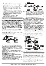
In programming mode is used for increasing the
values to be set and for selecting the parameters. In
programming mode can be used together with
key to
change parameters level.
4.
:
Pressed and released displays the limit temperatures
measured by the instrument (min: Lt and max.: Ht).
In programming mode
is used to return to normal
operation.
5. LED dp:
During the normal operation is the decimal
point. In programming mode, while the parameter code
is displayed, the dot indicates the parameter protection
level:
not protected
(lit up),
protected
(flashing) and
hidden
(turned OFF).
6. LED :
Indicates the
alarm status
:
ON
(lit),
OFF
(turned OFF) or
silenced
(flashing).
2. PROGRAMMING
2.1
Standard mode parameters programming
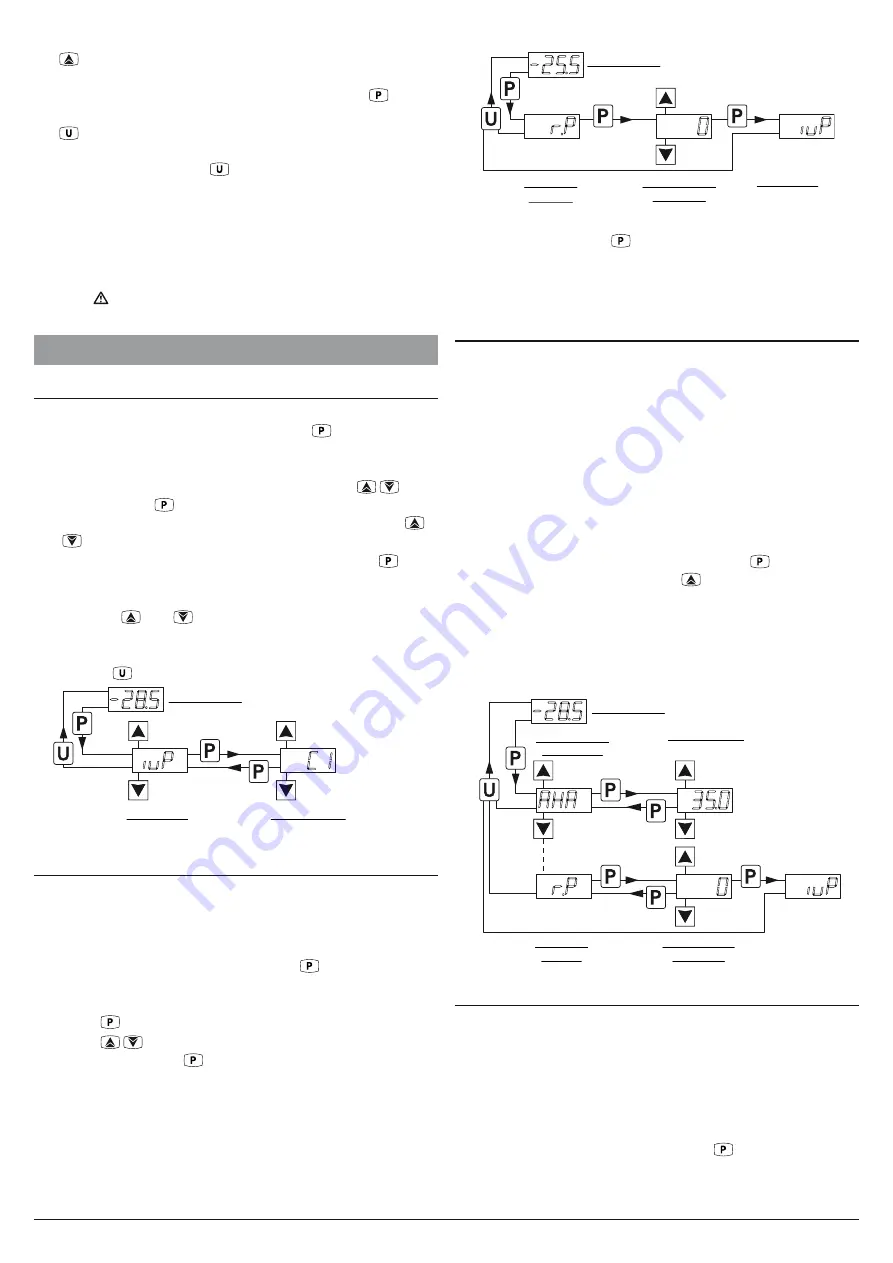
To access the instrument function parameters when pass-
word protection is disabled, press the key
and keep it
pressed for about 5 seconds, after which the display shows
the code that identifies the first programmable parameter
The desired parameter can be selected using the
/
keys,
then, pressing the
key, the display shows the parameter
code alternated to its value that can be changed with the
and
keys.
Once the desired value has been set, press the key
again: the new value is stored and the display shows only
the code of the selected parameter.
Pressing the
and
keys, it is possible to select another
parameter and change it as described.
To exit the programming mode, press no keys for about 30 s
or keep the
key pressed for 2 s.
Previous
Param.
Normal mode
Parameters
(Program mode)
Set parameter
Next
Param.
2 s
5 s
Increase
value
Decrease
value
-28.5
iup
C1
2.2
Parameter protection using the password
The instrument has a parameter protection function using a
password that can be personalised through the
tPP
parameter
To protect the parameters, set the desired password number
at the parameter
tPP
.
When the protection is active, press the
key to access
the parameters and keep it pressed for about 5 s, after which
the display shows
r.p
.
Press the
key, the display shows
0
.
Using the
/
keys, insert the programmed password
number and press the
key
again.
If the password is correct the instrument displays the code
of the first parameter at this point i possible to program the
instrument in the same way previously described.
The password protection can be disabled by setting
tPP
=
oF
.
Normal mode
2 s
5 s
Increase
value
Decrease
value
-25.5
r.p
0
iup
Password
Request
Insert Correct
Password
Parameters
(Program mode)
Note:
If the Password gets lost, just switch
OFF
then
ON
the
instrument, push
key during the initial test keeping
it pressed for 5 s. In this way it is possible to access all
the parameters, verify and modify the parameter
tPP
.
2.3
Customized mode parameter programming
(parameters programming level)
By the instrument factory setting the password protection func-
tion affects all parameters. To make a parameter accessible
without having to enter the password when
tPP
password
protection is activate, use the procedure that follows:
–
Enter the program mode using the
tPP
Password;
–
Select the parameter that must be accessible (no pass-
word protection);
–
Once a parameter is selected, if the
dp LED flashes
, the
parameter is programmable by entering the password (is
“
protected
”). If the
dp LED is steady ON
the parameter
is programmable without password (is “
unprotected
”).
–
To change the parameter visibility, press the
key and
keeping it pressed also press the
button. The
dp LED
changes its state indicating the new level of parameter acces-
sibility (
ON
= not protected;
flashing
= password protected).
In case some parameters are not protected, accessing
the the programming mode the display first shows the not
protected parameters, then the
r.p
parameter (through which
will be possible to access the “protected” parameters).
Normal mode
2 s
5 s
Increase
value
Decrease
value
-28.5
r.p
Previous
Param.
Not protected
parameters
Set Parameter
Password
request
Insert correct
password
Parameters
Program Mode
Next
Parameter
Increase
value
Decrease
value
AHA
35.0
0
iup
2.4
Reset parameters to default value
The instrument allows the reset of the parameters to values
programmed in factory as default
To restore the default parameters value set value
-48
at
r.p
password request Therefore, to make the reset to the default
parameters, enable the Password using the
tPP
parameter
so that the
r.p
setting is requested, at this point insert
-48
instead of the programmed access password.
Once confirmed the password with the
key the display
shows “
---
” for 2 s therefore the instrument resets all the
parameters to factory default setting.

