Ascon Tecnologic - e30V - OPERATING INSTRUCTIONS - PAG. 4
4.3
Electrical connections
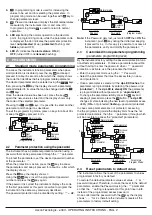
Carry out the electrical wiring by connecting only one wire to
each terminal, according to the following diagram, checking
that the power supply is the same as that indicated on the
instrument and that the load current absorption is no higher
than the maximum electricity current permitted.
As the instrument is built-in equipment with permanent con-
nection inside housing, it is not equipped with either switches
or internal devices to protect against current overloads: the
installation will include an overload protection and a two-
phase circuit-breaker, placed as near as possible to the in-
strument and located in a position that can easily be reached
by the user and marked as instrument disconnecting device
which interrupts the power supply to the equipment
It is also recommended that the supply of all the electrical cir-
cuits connected to the instrument must be protect properly, us-
ing devices (ex. fuses) proportionate to the circulating currents.
It is strongly recommended that cables with proper insulation,
according to the working voltages and temperatures, be used.
Furthermore, the input cable of the probe has to be kept sepa-
rate from line voltage wiring. If the input cable of the probe is
screened, it has to be connected to the ground at only one side.
4.3.1
Electrical wiring diagram
Supply
1
3
2
4 5 6
INPUT
Pr1
5. FUNCTIONS
5.1
Measure and display configuration
With the
iuP
it is possible to select the temperature engi-
neering unit and the desired measure resolution (
C0
= °C/1°;
C1
= °C/0.1°;
F0
= °F/1°;
F1
= °F/0.1°).
The instrument allows the measure calibration, which can
be used to recalibrate the instrument according to applica-
tion needs, The calibration is made by using parameters
iC1
(input Pr1).
5.2
Alarm functions
The alarm conditions of the instrument are:
–
Probe errors
E1
,
-E1
;
–
Temperature alarms
Hi
and
Lo
;
The alarm functions act on the LED .
Any active alarm condition is signaled lighting up the LED ,
while the acknowledged alarm status is shown by flashing the
LED .
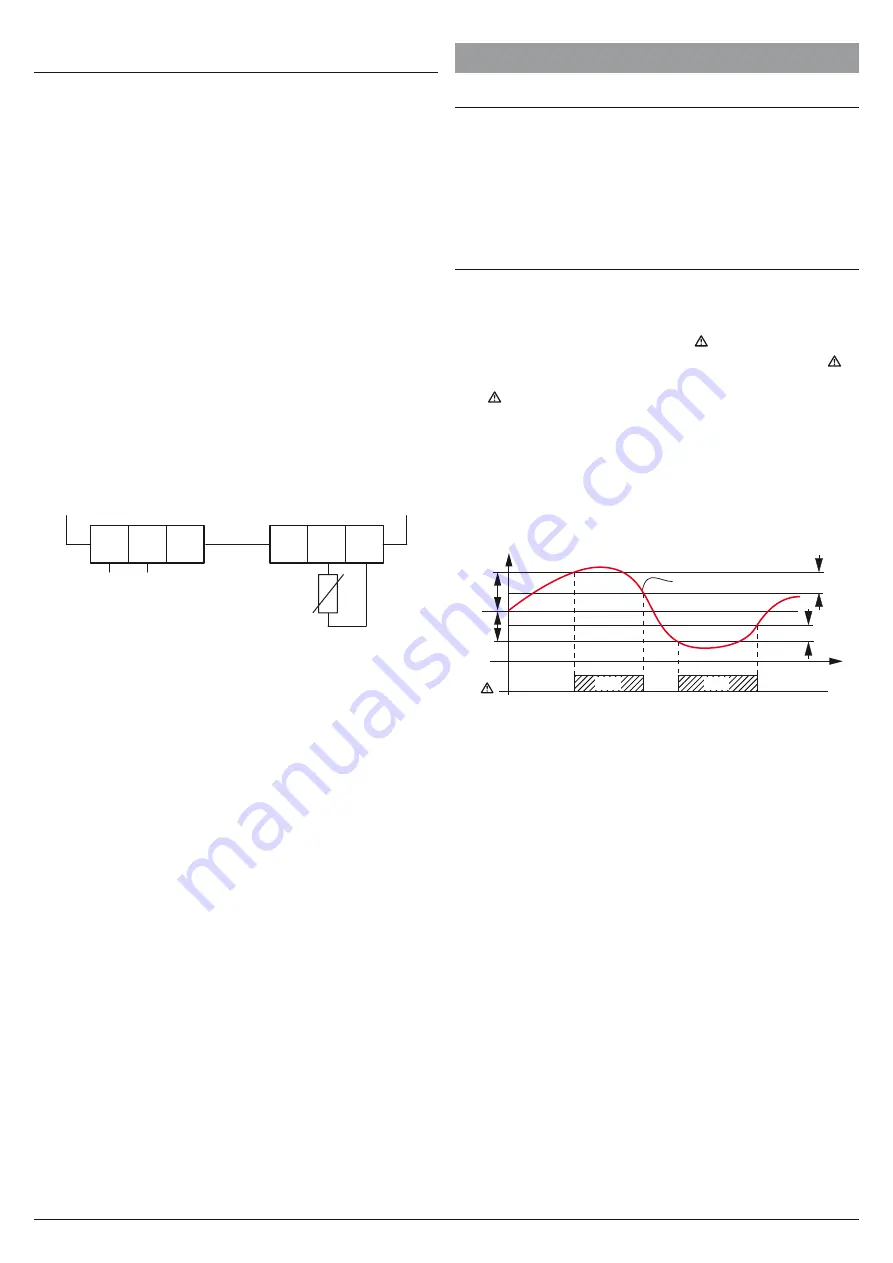
5.2.1
Temperature alarms
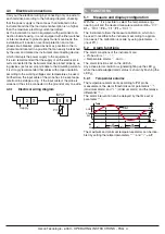
The temperature alarm works according to
Pr1
probe
measurement, the alarm thresholds set at parameters
AHA
(maximum alarm) and
ALA
(minimum alarm) and the relative
differential
AAd
.
The alarm intervention can be delayed by the time set at
parameter
AAt
.
AHA
SP
ALA
off
off
off
ON
ON
Hi
Lo
Temp.
time
AL
AAd
AAd
Pr1
The maximum and minimum temperature alarms can be disa-
bled by setting the related parameters
AHA
and
ALA
=
oF
.

