Ascon Tecnologic - Z31V - OPERATING INSTRUCTIONS - PAG. 2
1.2
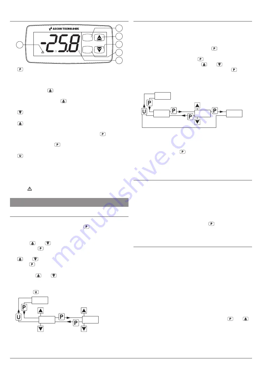
Front panel description
P
U
Z31V
1
5
3
2
4
6
1.
:
Hold pressed for 5 s allows access to the param-
eters programming mode. In programming mode it is
used to access the parameters editing and for the values
confirmation. In programming mode it can be used to-
gether with the
key to change the programming level
of the parameters. When the keyboard is locked, it can
be used together with
key (both pressed for 5 s) key
to unlock the keyboard.
2.
:
In programming mode is used for decreasing the
values to be set and for parameters selection.
3.
:
In programming mode is used for increasing the val-
ues to be set and for parameters selection. In program-
ming mode can be used together with key
to change
parameters level. When the keyboard is locked, it can be
used together with
key (both pressed for 5 s) key to
unlock the keyboard
4.
:
Pressed and released causes the display of the in-
strument variables (measured temperatures etc.). In pro-
gramming mode can be used to return in normal mode.
5. LED SET:
In normal mode indicates when a key is
pressed. In programming mode indicates the param-
eters programming level.
6. LED
:
Indicates the alarm status:
active
(on),
not ac-
tive
(off) or
silenced
(flashing).
2. PROGRAMMING
2.1
Parameters programming
To access the instrument operating parameters when pass-
word protection is disabled, press the
key and keep it
pressed for about 5 seconds, after which the display shows
the code that identifies the first parameter.
Using the
and
keys, select the desired parameter
and press the
key, the display will show the parameter
code alternated to its setting value that can be changed with
the
and
keys. Once the desired value has been set,
press the
key again: the new value will be stored and the
display will show again the selected parameter code only.
Pressing the
and
keys, it is possible to select another
parameter and change it as described.
To exit the programming mode, press no keys for about 30 s
or keep the
key pressed for 2 s.
Previous
Param.
Normal
mode
Parameter selection
(Programming mode)
Parameters set
Next
Param.
2 s
5 s
Increase
value
Decrease
value
-25.5
-25.5
s.Ls
s.Ls
-30.0
-30.0
2.2
Parameter protection using a password
The instrument has a parameter protection function using a
password that can be personalised, through
t.PP
parameter.
To protect the parameters, set the desired password number
at
t.PP
parameter.
When the protection is active, press the
key to access
the parameters and keep it pressed for about 5 s, after which
the display shows
r.P
. Press the
key again, the display
will show
0
, at this point, using the
and
keys, set the
programmed password number and press the key
again.
If the password is correct the instrument displays the code of
the first parameter and it will be possible to program the in-
strument in the same way described in the previous section.
Normal
mode
2 s
5 s
Increase
value
Decrease
value
-25.5
-25.5
r.p.
r.p.
0.
0.
s.ls
s.ls
Password
request
Insert the
correct password
number
Parameters
(programing mode)
The password protection can be disabled by setting the
parameter
t.PP
=
oF
.
Note:
If the Password gets lost, just switch OFF and ON the
instrument, push
key during the initial test keeping
it pressed for 5 s. In this way it will be possible to ac-
cess all the parameters, verify and modify the param-
eter
t.PP
.
2.3
Reset parameters to default value
The instrument allows the reset all the parameters to those
values programmed in factory as default.
To restore the default parameters value, simply set the value
-48
at
r.P
password request.
Therefore, to do the reset, enable the Password using the
t.PP
parameter in order to turn ON the
r.P
password request,
then set
-48
instead of the programmed password.
Once confirmed the password with the
key the display
shows “
---
” for about 2 s, then the instrument resets all the pa-
rameters and restores their factory-programmed default values.
2.4
Keyboard lock function
On the instrument it is possible to completely lock the keyboard.
This function is useful when the instrument is in an accessible
area and the changes must be avoided.
To activate the keyboard lock it is enough program the pa-
rameter
t.Lo
to a value different than
oF
.
The
t.Lo
value is the keys inactivity time after which the key-
board will be automatically locked.
Therefore, pressing no keys for the time set at
t.Lo
param-
eter the instrument automatically disables the normal func-
tions of the keys.
When the keyboard is locked, if any of the key is pressed,
the display shows
Ln
to warn that the lock is active.
To unlock the keyboard it is enough to press the
and
keys at the same time and keep them pressed for 5 s, after
which the label
LF
appears on the display and all the key
functions will be available again.


