Ascon Tecnologic - Z31V - OPERATING INSTRUCTIONS - PAG. 3
3. USAGE WARNINGS
3.1
Admitted use
m
The instrument has been projected and manufactured
as a measuring and control device to be used accord-
ing to EN61010-1 at altitudes operation below 2000 m.
Using the instrument for applications not expressly permitted
by the above mentioned rule must adopt all the necessary
protective measures.
The instrument
must not be used
in dangerous environ-
ments (flammable or explosive) without adequate protections.
m
The installer must ensure that the EMC rules are
respected, also after the instrument installation, if
necessary using proper filters.
4. INSTALLATION WARNINGS
4.1
Mechanical mounting
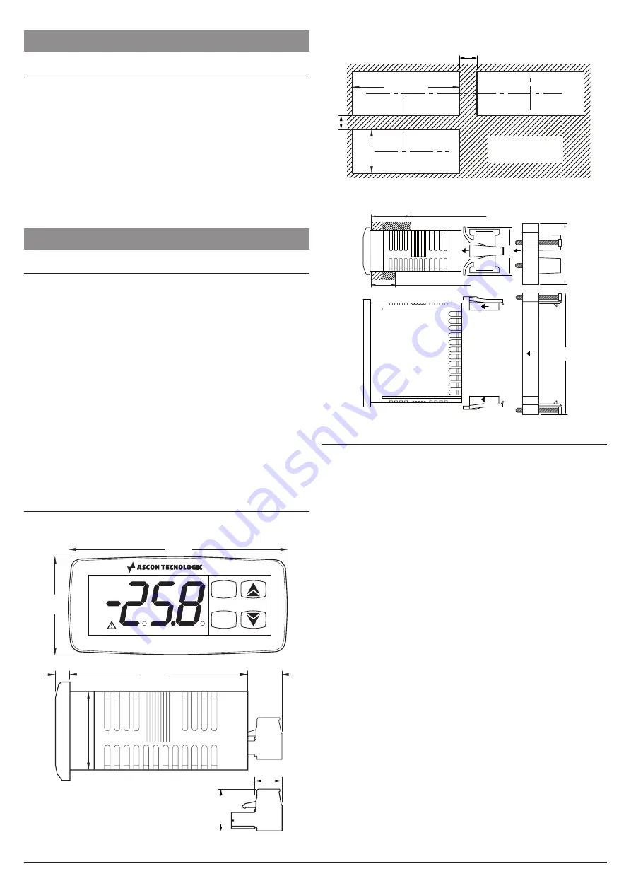
The instrument, in case 78 x 35 mm, is designed for flush-
in panel mounting. Make a 71 x 29 mm hole and insert the
instrument, fixing it with the provided special brackets.
To obtain the declared front protection degree please use the
optional screw type bracket.
–
Avoid installing the instrument in places with high humidity
which can generate condensation or with dirt which can
lead to the introduction of conductive substances into the
instrument.
–
Ensure the adequate ventilation to the instrument and avoid
the installation within boxes where are placed devices which
may overheat or have, as a consequence, the instrument
functioning at temperature higher than allowed and declared.
–
Connect the instrument as far as possible from source of
electromagnetic disturbances so as motors, power relays,
relays, electrovalves, etc..
4.2
Dimensions
[mm]
4.2.1
Mechanical dimensions
P
U
Z31V
35
78
28
12.2
14.5
8
6
64
4.2.2
Panel cut-out
29
+0.6
71
+0.6
mm
RECOMMENDED
PANEL CUTOUT
min.
12 mm
min. 15 mm
4.2.3
Mounting
[mm]
Type 2: gasket max. 12 mm
Type 1: gasket 29 mm max.
34
43
Type 2
Type 1
“Butte
rf
ly” type
bracket
s
Screw type
bracket
86
4.3
Electrical connections
Carry out the electrical wiring by connecting only one wire to
each terminal, according to the following diagram, checking
that the power supply is the same as that indicated on the
instrument and that the load current absorption is no higher
than the maximum electricity current permitted.
As the instrument is built-in equipment with permanent con-
nection inside housing, it is not equipped with either switches
or internal devices to protect against current overloads: the
installation will include an overload protection and a two-
phase circuit-breaker, placed as near as possible to the in-
strument and located in a position that can easily be reached
by the user and marked as
instrument disconnecting
device
which interrupts the power supply to the equipment.
Further recommendations:
–
The supply of all the electrical circuits connected to the
instrument must be properly protected using devices (ex.
fuses) proportionate to the circulating currents;
–
Use cables with proper insulation, according to the working
voltages and temperatures;
–
Make sure that the input sensor cables are kept separate
from line voltage wiring in order to avoid induction of elec-
tromagnetic disturbances;
–
If some cables are shielded, the protection shield must be
connected to ground at only one side;
–
If the instrument has a 12/24 V power supply (Order Code
a
=
F
/
G
), it is recommended to use an external TCTR
transformer, or an equivalent transformer with a Class II
Insulation, and to use a transformer for each instrument
because there is no insulation between supply and input.


