Ascotel® IntelliGate® 2025/2045/2065 as of I7.9
150
Installation
sy
d-
020
4/1.
7
– I7.
9
– 1
2
.2009
4. 7. 5. 8
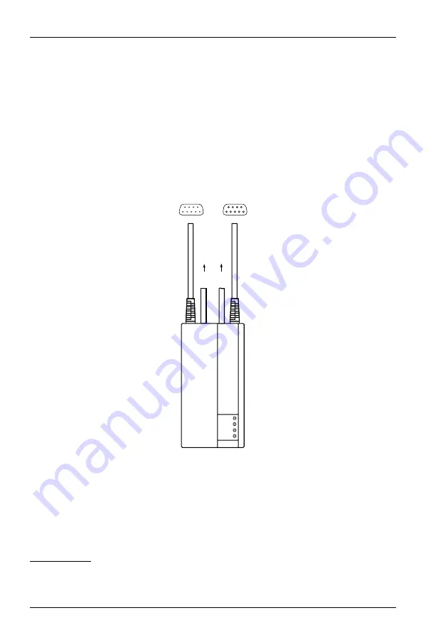
V.24 interface on the Pocket Adapter (PA)
The PA provides a V.24 interface for connecting an AD2 interface with a PC. The PA's
V.24 cable is connected to a serial interface on the PC
1)
.
Two terminals can be connected to an AD2 interface. An system terminal can be
connected via the PA. The PBX differentiates the two terminals on the basis of the
position of DIP switch S2 on the PA (see
) and the setting of the terminal se-
lection digit (TSD) on the system terminal. Both terminals must have a different
TSD.
Fig. 86
LED displays and connections on the Pocket Adapter
Settings
The same communication parameters must be set on all the connected equip-
ment. On the PA this is done using DIP switches S1... S8 (see
1)
PA Version
V2.4
RX A
TX A
TX B
RX B
T
erminal
PBX
AD2
AD2
V
.24 (A)
V
.24 (B) (PC / Printer)
V.24 D-Sub-9
female
9
6
6
9
male
5
1
1
5
haz1143aaena0


