Ascotel® IntelliGate® 2025/2045/2065 as of I7.9
78
Installation
sy
d-
020
4/1.
7
– I7.
9
– 1
2
.2009
5.
Fit the battery cable without battery connected to the UPS-12V module. Make
sure the polarity is correct!
6.
Connect the UPS-12V module with the PBX. To do that connect the cable to the
primary connector and secondary connector (see
7.
Use the provided screws to fasten the UPS-12V module to the angle bracket.
8.
Secure the cover to the power supply area.
9.
Connect the PBX to the 230 VAC power supply.
10.
Connect the battery. Make sure the polarity is correct!
11.
Check the UPS functions by interrupting the 230 VAC power supply for a few
minutes. The PBX must continue to run without interruption. The event message
PBX power suply
is displayed after a few seconds.with the parameter
Battery
.
The battery capacity is rated according to the power requirements and the re-
quired bridging time of the PBX.
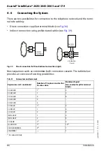
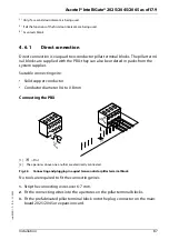
Tab. 26
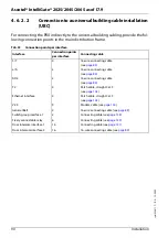
Power requirements of the PBX and battery rating (12 V)
Note:
It is also possible in principle to supply the PBX with the UPS-12V module
via a centralized 12 VDC system.
Basic system
Maximum power
requirements for PBX
(+ ATPS)
Battery capacity (Ah)
1)
for stored energy time
1)
Maximum configuration and maximum traffic volume. Typical conditions require approx. 60% of the speci-
fied battery capacity
OC
W
1 h
4 h
12 h
Ascotel® IntelliGate® 2025/2045
110
70
10
30
90
Ascotel® IntelliGate® 2025/2045 + ATPS
2)
2)
Only one external USP is possible when using the ATPS
180
140
20
60
180
Ascotel® IntelliGate® 2065
210
135
20
60
180
Ascotel® IntelliGate® 2065 + ATPS
460
420
60
180
540


