Ascotel® IntelliGate® 2025/2045/2065 as of I7.9
84
Installation
sy
d-
020
4/1.
7
– I7.
9
– 1
2
.2009
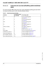
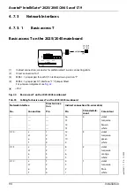
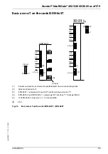
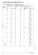
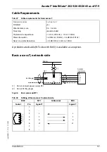
Tab. 29
Example of component placement with Ascotel® IntelliGate® 2045
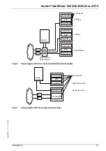
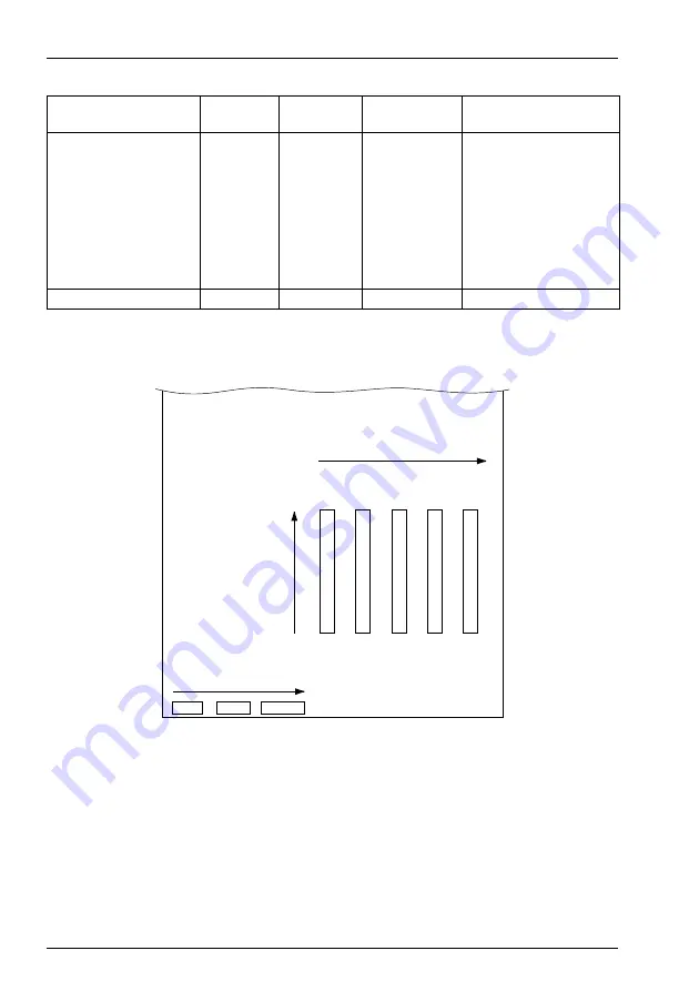
The figure below uses the complement placement example Ascotel® IntelliGate®
2045 to illustrate the sequence in which interfaces are enabled:
Fig. 34
Activation of the interfaces using the example of component placement on Ascotel® Intelli-
Gate® 2045
Location
Card
Network
interfaces
Endgeräte-
schnittstellen
Note
2025/2045 basic system
(MBS)
2
8
(2xT, 1xS, 3xab, 4xAD2)
Expansion slot 1
OI-2DOOR
-
-
for door intercom
Expansion slot 2
VM-02P
-
2
Voice Mail System AVS 5150
Expansion slot 3
SC-08AD2
-
8
of which 4 interfaces are
used for radio units
Expansion slot 4
DSP-02
-
-
DECT channels
Expansion slot 5
AIP -6500
-
16
No permanently allocated
terminal interfaces
Total
2
34
Ascotel IntelliGate 2045
2. Activation of the expansion cards
Expansion slots
haz1341aaenc0
1
3 x a/b
4 x AD2
3 x S/T
2
3
4
5
1. Activation of the interfaces
on the Main board
Activation of the interfaces
on the expansion cards
OI-2DOOR
VM- 02P
SC-08AD2
DSP-02
AIP
6500


