Asentria SiteBoss 571 UserManual
Page 10
1
– Empty slot for a single 30-Amp circuit-breaker-protected power output, or 3 additional 10-Amp fused power
outputs.
Internal
On-board temperature sensor
Internal lithium coin-cell type battery backup*/**
*
Battery backup preserves clock operation when power is not present. Data records and settings are stored in
non-volatile memory and therefore do not require battery backup.
CAUTION: THERE IS A RISK OF EXPLOSION IF THE BATTERY IS REPLACED BY AN INCORRECT TYPE. Replace
with batteries of the same type or as recommended by the manufacturer. Dispose of used batteries
according to the instructions.
Lithium batteries can be recycled. Contact a recycling organization in your
area for details.
ATTENTION: II y a danger d’explosion s’il y a remplacement incorrect de la batterie. Remplacer
uniquement avec une batterie du même type ou d’un type equivalent recommandé par le constructeur.
Mettre au rebut les batteries usagées conformément aux instructions du fabricant.
In addition to the above standard on-board equipment, the S571 may be shipped with the following accessories:
Documentation and Utilities CD
6 ft. RJ45 M-M unshielded serial cable serial cables
RJ45/DB9 Male DTE Adaptors
RJ45/DB9 Female DCE Adaptor
Rack mount ears
Screwdriver and terminal blocks for Expansion Cards with internal contacts
Options
Each of the following components is optional and may be installed on an S571:
1 or 2
– Expansion Cards of various configurations to install in either or both of the Expansion Card slots
1
– Wireless modem (installed in one of the two Expansion Card slots)
1
– 30Amp power output, or 3 – 10Amp power outputs
1
– AISG interface
I/O points and Expansion Cards
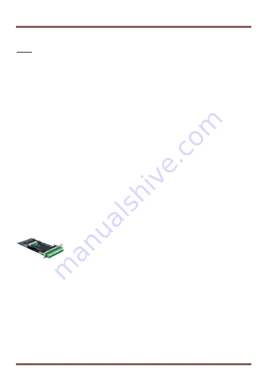
Fig 3: Expansion Card
The expansion cards in the two expansion card slots can be configured with multiple options. The letters over
the terminal block ports indicate how the slot is configured. A single card can be configured for more than one
type of IO option.
C
– Standard Contact Closure Input
CI
– Isolated Contact Closure Input
V
– Analog Voltage Input
VI
– Isolated Voltage Input
M
– 4-20mA Current Input
MI
– Isolated 4-20mA Current Input
R
– Low-Current Relay
SR
– Solid State Relay
F
– Resistive fuel sensor
P
– +/-15 VDC Power Output
P5
– + 5 VDC Power Output


