Asentria SiteBoss 571 UserManual
Page 11
Other types of cards can be installed into the expansion card slots including a wireless modem, serial port
cards, high-density expansion cards, and a GPS receiver.
Fig 4: Wireless Modem Fig 5: Serial Port Card Fig 6: High-Density I/O Card
AISG interface
The optional AISG module allows a user to tilt an antenna remotely. AISG stands for Antenna Interface Standards
Group. They created open specifications for antenna control. For more information on this option please see the
AISG Remote Antenna Controller
Feature Guide available on the Asentria Product Information Portal or contact
Ports, Connectors, LEDs and Buttons
Front Panel Ports and Connectors
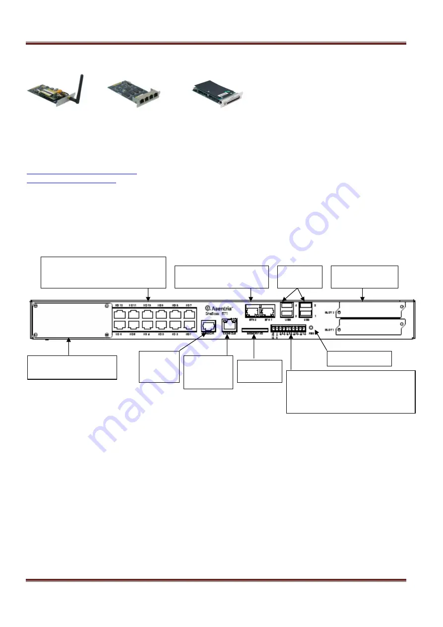
The basic S571 front panel is shown below.
Fig 7: S571 Front panel ports and connectors
Serial Ports
Each of the twelve (or more) serial ports and one Console port are configured as a DTE port using an RJ-45
connector. This is the standard recommended pinout for EIA/TIA-561 for 8 pin RJ45 connector:
PIN1
=RI
=RING INDICATOR, INPUT to the S571
PIN2
=DCD =CARRIER DETECT, INPUT to the S571
PIN3
=DTR =DATA TERMINAL READY, OUTPUT from the S571
PIN4
=SIGNAL GROUND
PIN5
=RXD =RECEIVED DATA, INPUT to the S571
PIN6
=TXD =TRANSMITTED DATA, OUTPUT from the S571
PIN7
=CTS =CLEAR TO SEND, INPUT to the S571
PIN8
=RTS =REQUEST TO SEND, OUTPUT from the S571
The DB9 male cable end of the adaptor which mates with the serial port connectors of connected devices will often
have a pair of screw-down cable screws. These cable screws should be used to assure a solid connection of the
cable with the device.
12
– RJ45 serial data I/O ports
Left to right: Top row: #12 thru #7
Bottom row: #6 thru #1
RJ45 serial
Console
port
RJ45
ES Bus
port
2
– RJ45 Ethernet ports
Left to right: #2, #1
Empty slot for optional
AISG interface
2
– Expansion
Card bays
4
– USB
ports
Memory
IO slot
4 pair of contact points plus a
power output
Far Left: 1 - 12V DC power output
Right: 4 pair dry contacts
Reset button


