background image

12

AEU-350 / AEU-350S

CONTROL PANEL

A

B

C

D

E

F

G

H

J

I

K

L

M

N

O

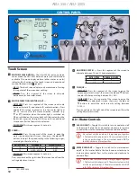
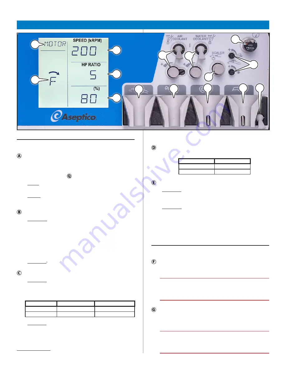
Touch Screen


MOTOR / SCALER  MODE


 —

 The AEU-350 has only one mode, 

motor mode; the AEU-350S has both motor and scaler modes 

available.  The mode displayed here (either motor or scaler) 

indicates the functions of the touch screen and operational 

mode of the footswitch   (page 13). 
• 

AEU-350

: The touch screen displays only motor mode. Pressing 

this segment of the screen does nothing.

• 

AEU-350S

: Press this segment of the screen to alternate 

between motor and scaler modes. 


MOTOR DIRECTION / MOTOR LIGHT   —


• 

MOTOR MODE

: Press this segment of the screen to alternate 

between forward (F) and reverse (R) motor directions. Press 

and hold this screen segment to turn the motor light on/

off. An asterisk after the motor direction indicator (e.g. 

F

*

 or R

*

) indicates when the motor light is switched on. 

When switched on, the motor light will illuminate when the 

footswitch is pressed; the light will stay on for an additional 

20 seconds after the footswitch is released.

• 

SCALER MODE

1

: This screen segment is not used.


SPEED   —


• 

MOTOR MODE

: Press this segment of the screen to open the 

motor speed adjustment screen, then press the 

 and 


buttons to adjust the speed setting in the following ranges, 

according to the ratio setting: 

RATIO SETTING

SPEED RANGE

SPEED DISPLAYED

 1:5

25,000–200,000

25–200

 1:1

 5,000–40,000 

5–40

• 

SCALER MODE

1

: This screen segment is not used.


Press anywhere on the right side of the screen to exit from the 

setting adjustment screen.

AEU-350S only


HANDPIECE RATIO  —

 Press this segment of the screen to 

alternate between 1:5 and 1:1 handpiece ratios: 

RATIO SETTING

NUMBER DISPLAYED

 1:5

 5

 1:1

1


TORQUE   —


• 

MOTOR MODE

: Press this segment of the screen to open the 

torque adjustment screen, then press the 

 and 

 buttons 

to adjust the torque setting between 30–100%.

• 

SCALER MODE

1

: Press this segment of the screen to open the 

scaler intensity adjustment screen, then press the 

 and 

 buttons to adjust the scaler intensity setting between 

5–100%.


Press anywhere on the right side of the screen to exit from the 

setting adjustment screen.

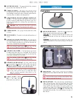
Air / Water Controls


AIR COOLANT


 —

 Toggle this switch to turn air coolant on/off 

to the motor. Rotate the knob counter-clockwise to increase 

air coolant flow to the motor and clockwise to decrease flow. 


Air  coolant only flows when 3 things happen together:  

1. The footswitch is depressed, 2. The air coolant switch is 

in the on position (up), 3. The air coolant knob is NOT in 

the fully-clockwise (closed) position.


WATER COOLANT


 —

 Toggle this switch to turn water coolant 

on/off to the motor. Rotate the knob counter-clockwise to 

increase water coolant flow to the motor and clockwise to 

decrease flow.


Water coolant only flows when 3 things happen together:  

1. The footswitch is depressed, 2. The water coolant switch 

is in the on position (up), 3. The water coolant knob is NOT 

in the fully-clockwise (closed) position.

Summary of Contents for 120426

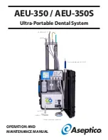
Page 1: ... Scaler included with AEU 350S Shown with optional equipment OPERATION AND MAINTENANCE MANUAL AEU 350 AEU 350S Ultra Portable Dental System AHP 72MK FO AHP 101 AHP 53 ...

Page 2: ...ugh the water sys tem saline will corrode the plumbing s WARNING Ultrasonic scaler instrument tips oscillate at high frequency and can fracture during operation To help prevent the tips from fracturing and possibly injuring the patient always follow the scaler manufacturer s operating instructions and rec ommended ultrasonic power settings s WARNING Do not use an ultrasonic scaler dry If used dry ...

Page 3: ...and 1 5 handpieces 200 000 RPM max Large easy to read touch screen display Complies with international carry on luggage size restrictions Weighs only 34 lb 15 5 kg Compact operation mode provides quick setup operation ready within 5 minutes Expanded operation mode provides easy access to instruments from a standing position Self contained water system with 500ml water bottle capacity 750ml waste c...

Page 4: ...uch P N 410225 q Micro motor P N AE 242SC 40 q Footswitch P N AE 7PM q Power Cord P N 840041 q Power Cord Pouch P N 410222 q Syringe P N TA 90D permanently attached to unit q Syringe Tip P N TA 1 q HVE High Volume Ejector Valve and Hose Assembly P N AA 350 HVE q Saliva Ejector Low Volume Valve and Hose Assembly P N AA 350 SAL ...

Page 5: ...0S only Thin Subgingival P N ASC 10 PE37 Slim Universal P N ASC 10 PE38 Power Universal P N ASC 10 PE39 SOLD SEPARATELY q 24 VDC Battery Power Cord P N AA 350 BATCAB Optional equipment NOTE Powering the unit from a 24 VDC battery is optional and will provided limited operation time depending on battery type and capacity A high performance 8 AH battery can provide up to 2 hours of active use A gen ...

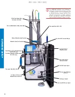
Page 6: ...nly Auxiliary Water Port Adjustment AEU 350 only Syringe Air and Water Controls Air Reserve Tank w Bleed Valve on bottom Universal AC Power Input Power Input Selector AC DC AC Power Switch EXPANDED SETUP The EXPANDED SETUP has the advantage of making the instruments easy to reach even from a standing position It has the disadvantage of not having automatic vacuum actuators in the HVE and saliva ej...

Page 7: ...r Low Volume Ejector HVE High Volume Ejector Electric Motor Scaler Settings Touchscreen Water Supply Bottle Waste Container Footswitch Air Filter Scaler and Scaler Holder AEU 350S only COMPACT SETUP The COMPACT SETUP has the advantages of a quicker setup and automatically actuated HVE and saliva ejector instrument holders ...

Page 8: ...ead The AEU 350 features an auxiliary water port B and the AEU 350S features a scaler which is per manently attached at this location B A B 3 Connect the footswitch plug A to its socket on the bulkhead behind the air tank B The footswitch plug has a notch C and can only be inserted into the socket in one orientation Hold the plug against the socket and rotate it until you feel the plug enter the s...

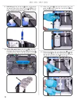
Page 9: ...t in one orientation The dimple B on the plug must line up with the groove C on the socket while inserting A B C 7 Place the syringe A motor B saliva ejector C and HVE D into their instrument holders A B C D 8 Lift up the unit to the vertical position with the door open Place the footswitch A where it is convenient to operate A ...

Page 10: ...handle B until it locks in the extended position Clip the 4 position instrument holder C onto the handle Move the 4 instruments to the upper holder A B C 11 Fill the water bottle A with water never saline Insert the uptake tube B into the bottle then screw the bottle C into the fitting on the bulkhead A B C 12 While pressing down on the spring loaded lever A insert the waste container B into the w...

Page 11: ... grounded AC outlet Set the AC power switch to the on 1 position to turn on the unit C A B 15 Optional 24VDC Operation Unplug the AC power cord A and set the input selection switch B to the AC not DC posi tion Plug the DC power cord into the DC input C then connect the DC power cord s red clip to the positive pole and the black clip to the negative pole of a 24V battery The input selection switch ...

Page 12: ...000 5 40 SCALER MODE1 This screen segment is not used Press anywhere on the right side of the screen to exit from the setting adjustment screen 1 AEU 350S only HANDPIECE RATIO Press this segment of the screen to alternate between 1 5 and 1 1 handpiece ratios RATIO SETTING NUMBER DISPLAYED 1 5 5 1 1 1 TORQUE MOTOR MODE Press this segment of the screen to open the torque adjustment screen then press...

Page 13: ...e up position to enable the automatic vacuum switch AUTOMATIC HOLDER LOCKOUT Set this switch to the up position to enable the automatic switches in the saliva ejector and HVE ejector holders Set in the down position to disable the automatic switches and turn off the vacuum When using the 4 position secondary instrument holder for the saliva and HVE ejectors see Expanded Setup page 6 use the automa...

Page 14: ...epeat for the remaining ejector line Purge the lines of liquid Rinse the waste container with clean water The saliva and HVE ejector valves are autoclavable using any one of the STERILIZATION METHODS listed on page 15 The ejector hoses are not autoclavable CAUTION Use only non foaming cleansers in the vacuum lines Foam can get sucked into the vacuum pump causing permanent damage and voiding the wa...

Page 15: ...oid the warranty STERILIZATION METHODS Wrapped Sterilization Place in an appropriately sized steriliza tion pouch and seal A Standard autoclaving Gravity displacement method Time 15 min Temperature 132 C 270 F Dry time 30 minutes B Pre vacuum Dynamic air removal method Time 4 minutes Temperature 132 C 270 F Dry time 40 minutes Flash Sterilization For immediate use only C Unwrapped standard autocla...

Page 16: ... all water waste and clean sterilize the unit as instructed in Maintenance and Sterilization page 14 2 Unplug the power cord and coil 3 If used unclip the detachable 4 position and scaler instru ment holders from the case then retract the handle 4 Tip the unit on its back For shorter trips and quicker set up all instruments can be stowed in their holders as shown A with hoses and cables remaining ...

Page 17: ...s the handpiece Check if handpiece lubricant is draining into motor Touch screen error Switch off power wait 5 seconds then switch back on to reset Compressor shut down but vacuum pump running In case of overheating the compressor will shut down and the vacuum pump will run at low speed until the unit has cooled sufficiently SYMBOL DESCRIPTIONS Consult Instructions For Use Caution Consult Accompan...

Page 18: ...es arising from the clinical use of its products whether or not such use involves coincidental utilization of products manufac tured by others REPLACEMENT PARTS ITEM PART NUMBER Electric Motor Receptacle o ring kit AA240SC Electric Motor o rings x3 520069 Saliva Ejector Receptacle o ring 520130 Saliva Ejector Valve o ring kit AA 37LR HVE Receptacle o ring 520048 HVE Valve o ring kit AA 35LR Water ...

Page 19: ...een 2 The waste tank sensor will flash the version number of soft ware in the lower chamber One flash indicates version 1 two flashes indicates version 2 etc Error Messages None Fault Messages None WASTE DISPOSAL Dispose of all medical waste products residues etc in accordance with your local state and country laws Dispose of the unit and accessories at the end of life in accordance with your loca...

Page 20: ...1548 Woodinville WA 98072 8333 216th Street S E Woodinville WA 98072 Phone 425 487 3157 Toll Free 800 426 5913 Web www aseptico com Email info aseptico com P N 421222 Rev A ECO 15212 03 2021 Printed in the USA ...

Reviews: