Page 2
TABLE OF CONTENTS
Maintenance and Servicing Instructions
. . .3
Cleaning and Lubrication . . . . . . . . . . . . . . .3
Performance Verification . . . . . . . . . . . . . . .3
Inspection . . . . . . . . . . . . . . . . . . . . . . . . . . .3
Troubleshooting
. . . . . . . . . . . . . . . . . . . . . .3-4
Disassembly, Repair, Replacement,
Reassembly, and Check Out
. . . . . . . . . . . . .4-12
Compressor Chassis Removal . . . . . . . . . . .4
Compressor Removal . . . . . . . . . . . . . . . . . .6
Compressor Motor
Service Kit Installation . . . . . . . . . . . . . . . . .8
Aftercooler Fan Replacement . . . . . . . . . . .8
Aftercooler Assembly Replacement . . . . . . .9
Pressure Switch Replacement . . . . . . . . . . .10
Check Valve Replacement . . . . . . . . . . . . . .10
Removing the Air Storage Tank . . . . . . . . . .10
Replacing Pneumatic Tubing . . . . . . . . . . . .11
Removing Electronics Module . . . . . . . . . . .12
Removing the Intake Fan . . . . . . . . . . . . . . .12
Transformer Replacement . . . . . . . . . . . . . .12
Parts List
. . . . . . . . . . . . . . . . . . . . . . . . . . . .14-26
Case Base . . . . . . . . . . . . . . . . . . . . . . . . . . .14
Case Top, Inside . . . . . . . . . . . . . . . . . . . . . .14
Case Top, Outside . . . . . . . . . . . . . . . . . . . . .14
Compressor Chassis . . . . . . . . . . . . . . . . . . .16
Air Storage Tank . . . . . . . . . . . . . . . . . . . . . .16
Transformer . . . . . . . . . . . . . . . . . . . . . . . . . .18
Compressor . . . . . . . . . . . . . . . . . . . . . . . . . .18
Intake Fan . . . . . . . . . . . . . . . . . . . . . . . . . . .20
Aftercooler . . . . . . . . . . . . . . . . . . . . . . . . . .20
Motor Exhaust . . . . . . . . . . . . . . . . . . . . . . .22
Electronics Module . . . . . . . . . . . . . . . . . . . .22
Pressure Switch . . . . . . . . . . . . . . . . . . . . . . .22
Top Cover . . . . . . . . . . . . . . . . . . . . . . . . . . .24
Expendables . . . . . . . . . . . . . . . . . . . . . . . . .26
Table of Illustrations
Figure A: AA-75CF
Component Identification . . . . . . . . . . . . . .5
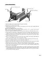
Figure B: Compressor Chassis Removal . . .5
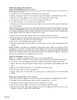
Figure Group C: Compressor Removal . . . .6
Figure D: Service Kit Installation . . . . . . . .7
Figure E: Aftercooler Removal . . . . . . . . . .9
Figure F: Pressure Switch Leads . . . . . . . . .11
Figure G: Tank Removal . . . . . . . . . . . . . . .11
Figure H: Intake Fan Removal . . . . . . . . . . .12
Figure I: Electronics Module . . . . . . . . . . . .12
Figure J: AA-75CF
System Wiring Schematic . . . . . . . . . . . . . . .13
Figure K: AA-75CF
System Pneumatic Schematic . . . . . . . . . . . .13
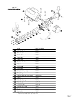
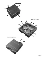
Figure 1: Case Base . . . . . . . . . . . . . . . . . . .15
Figure 2: Case Top, Inside . . . . . . . . . . . . . .15
Figure 3: Case Top, Outside . . . . . . . . . . . . .15
Figure 4: Compressor Chassis . . . . . . . . . . .17
Figure 5: Air Storage Tank . . . . . . . . . . . . . .17
Figure 6: Transformer . . . . . . . . . . . . . . . . . .19
Figure 7: Compressor . . . . . . . . . . . . . . . . . .19
Figure 8: Intake Fan . . . . . . . . . . . . . . . . . . .21
Figure 9: Aftercooler . . . . . . . . . . . . . . . . . .21
Figure 10: Motor Exhaust Chassis . . . . . . . .23
Figure 11: Electronics Module . . . . . . . . . . .23
Figure 12: Pressure Switch . . . . . . . . . . . . . .23
Figure 13A & B: Top Cover . . . . . . . . . . . . .25


